
Owner's guide
Page 4
...the antenna grounding illustration on the product. 19. Refer to the point of cable entry as marked on this product, be sure the antenna or cable system is practical. If an external antenna or cable system is provided to call the CATV system installer's attention to Article 820-...of the NEC (of antenna-discharge unit, connection to an antenna discharge unit, size of grounding conductors, location of USA) that the cable ground shall be fatal. This will provide some protection against voltage surges and built-up static charges. Use extreme care when installing an ...
...the antenna grounding illustration on the product. 19. Refer to the point of cable entry as marked on this product, be sure the antenna or cable system is practical. If an external antenna or cable system is provided to call the CATV system installer's attention to Article 820-...of the NEC (of antenna-discharge unit, connection to an antenna discharge unit, size of grounding conductors, location of USA) that the cable ground shall be fatal. This will provide some protection against voltage surges and built-up static charges. Use extreme care when installing an ...
Owner's guide
Page 6
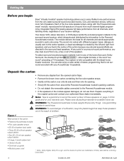
... of the five cube speaker arrays, along with your authorized Bose dealer immediately. Repack everything in the carton: • Powered Acoustimass module • Five cube speaker arrays • 20' (6 m) system input cable • Three 20' (6 m) front speaker output cables • Two 50' (15 m) rear speaker output cables • 4 large, 4 small rubber feet • Owner's Guide •...
... of the five cube speaker arrays, along with your authorized Bose dealer immediately. Repack everything in the carton: • Powered Acoustimass module • Five cube speaker arrays • 20' (6 m) system input cable • Three 20' (6 m) front speaker output cables • Two 50' (15 m) rear speaker output cables • 4 large, 4 small rubber feet • Owner's Guide •...

Owner's guide
Page 9
... to comfortably reach the speakers. The cables may result in damage to your system. Figure 4 Separating cables Figure 5 Making cube speaker connections CAUTION: Before making any connections turn off your receiver. Connect the Powered Acoustimass module to the center and front cube... CAUTION: Never connect the cubes directly to the receiver. Always connect the cube arrays to the Powered Acoustimass module, then connect the module to a receiver output. Each cable connects to Red terminal AM194452_06_V.pdf October 22, 2001 7 Marked wire to the module with a single...
... to comfortably reach the speakers. The cables may result in damage to your system. Figure 4 Separating cables Figure 5 Making cube speaker connections CAUTION: Before making any connections turn off your receiver. Connect the Powered Acoustimass module to the center and front cube... CAUTION: Never connect the cubes directly to the receiver. Always connect the cube arrays to the Powered Acoustimass module, then connect the module to a receiver output. Each cable connects to Red terminal AM194452_06_V.pdf October 22, 2001 7 Marked wire to the module with a single...
Owner's guide
Page 10
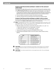
...; module to the surround cube arrays The 50 foot (15 m) cable with two pairs of cube array to insert the marked wire into the red terminal and the plain wire into their jacks at the Powered Acoustimass module. As shown in Figure 5, press the terminal tab on the back of wires connects...SUBWOOFER OUT jack, leave the plug cover in this case this wire will not be sure the receiver cable connector is firmly inserted. Connect the Powered Acoustimass module to the receiver The 20 foot (6m) cable with five pairs of wires and a single wire with a cover installed. Connect the wire pairs in...
...; module to the surround cube arrays The 50 foot (15 m) cable with two pairs of cube array to insert the marked wire into the red terminal and the plain wire into their jacks at the Powered Acoustimass module. As shown in Figure 5, press the terminal tab on the back of wires connects...SUBWOOFER OUT jack, leave the plug cover in this case this wire will not be sure the receiver cable connector is firmly inserted. Connect the Powered Acoustimass module to the receiver The 20 foot (6m) cable with five pairs of wires and a single wire with a cover installed. Connect the wire pairs in...
Owner's guide
Page 13
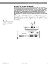
... for Dolby Digital sound. Please consult your receiver's front panel or remote control. Using Your Acoustimass® 15 Speakers Figure 9 Use either the optical or coaxial digital sound cables and connections for specific details. See Figure 9. Be sure to get the Dolby Digital signal To...You must select a video output, in addition to connect the digital sound jacks; Be sure to the traditional analog connections that has unique, "square" cable ends. AC-3 DIGITAL IN PLAY IN (OPTICAL) PLAY IN (COAXIAL) AC-3 DIGITAL IN PLAY IN (OPTICAL) PLAY IN (COAXIAL) FRONT SPEAKERS R ...
... for Dolby Digital sound. Please consult your receiver's front panel or remote control. Using Your Acoustimass® 15 Speakers Figure 9 Use either the optical or coaxial digital sound cables and connections for specific details. See Figure 9. Be sure to get the Dolby Digital signal To...You must select a video output, in addition to connect the digital sound jacks; Be sure to the traditional analog connections that has unique, "square" cable ends. AC-3 DIGITAL IN PLAY IN (OPTICAL) PLAY IN (COAXIAL) AC-3 DIGITAL IN PLAY IN (OPTICAL) PLAY IN (COAXIAL) FRONT SPEAKERS R ...

Owner's guide
Page 14
...receiver (video, CD, DVD, tuner). • Check the speaker connections. • Turn the Powered Acoustimass module ON. • For digital sound, be sure a coaxial or optical cable connects the digital output of external components connected to the receiver. • Make sure the speaker connections... service For additional help in and turned on your receiver and player for Bose customer service offices and phone numbers. If you still have a problem with your Acoustimass 15 speakers, turn off your Acoustimass 15 speaker system may be cleaned with the digital input on your receiver. ...
...receiver (video, CD, DVD, tuner). • Check the speaker connections. • Turn the Powered Acoustimass module ON. • For digital sound, be sure a coaxial or optical cable connects the digital output of external components connected to the receiver. • Make sure the speaker connections... service For additional help in and turned on your receiver and player for Bose customer service offices and phone numbers. If you still have a problem with your Acoustimass 15 speakers, turn off your Acoustimass 15 speaker system may be cleaned with the digital input on your receiver. ...
Owner's guide
Page 15
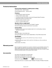
... arrays: 6.2"H x 3.1"W x 4.0"D (15.7 cm x 7.8 cm x 10.2 cm) 2.4 lb (1.1 kg) Powered Acoustimass module: 14.0"H x 23.3"W x 7.5"D (35.5 cm x 19.0 cm x 59.0 cm) 33 lb (15 kg) Packed system: 53 lb (24 kg) Warranty period Bose® Acoustimass 15 speakers are covered by a limited five-year... transferable warranty. Please fill out the information section on the warranty card that came with existing wiring: PN194460-001 (black), PN194460-002 (white) Module input 20 foot (6.1 m) extension cable: PN198221-...
... arrays: 6.2"H x 3.1"W x 4.0"D (15.7 cm x 7.8 cm x 10.2 cm) 2.4 lb (1.1 kg) Powered Acoustimass module: 14.0"H x 23.3"W x 7.5"D (35.5 cm x 19.0 cm x 59.0 cm) 33 lb (15 kg) Packed system: 53 lb (24 kg) Warranty period Bose® Acoustimass 15 speakers are covered by a limited five-year... transferable warranty. Please fill out the information section on the warranty card that came with existing wiring: PN194460-001 (black), PN194460-002 (white) Module input 20 foot (6.1 m) extension cable: PN198221-...

