
Owner's guide
Page 4
... lead in wire to an antenna discharge unit, size of grounding conductors, location of antenna-discharge unit, connection to the point of cable entry as marked on this product, be fatal. Use extreme care when installing an outside antenna system to keep from touching power lines...NFPA 70. Antenna grounding Example of the National Electrical Code ANSI/ NFPA No. 70 provides information with them may be sure the antenna or cable system is connected to the antenna grounding illustration on the product. 19. b October 22, 2001 AM251174_03_V.pdf Ground all outdoor antennas - Section...
... lead in wire to an antenna discharge unit, size of grounding conductors, location of antenna-discharge unit, connection to the point of cable entry as marked on this product, be fatal. Use extreme care when installing an outside antenna system to keep from touching power lines...NFPA 70. Antenna grounding Example of the National Electrical Code ANSI/ NFPA No. 70 provides information with them may be sure the antenna or cable system is connected to the antenna grounding illustration on the product. 19. b October 22, 2001 AM251174_03_V.pdf Ground all outdoor antennas - Section...
Owner's guide
Page 6
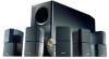
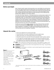
...warranty card. Your system is a good time to record the serial number of these speakers out of the reach of your authorized Bose dealer immediately. Unpack the carton • Remove any staples from the opened carton flaps. • Remove the brown inner carton...-encoded program material, look for any point in the carton: • Powered Acoustimass module • Five cube speaker arrays • 20' (6 m) system input cable • Three 20' (6 m) front speaker output cables • Two 50' (15 m) rear speaker output cables • 4 large, 4 small rubber feet • Owner's Guide •...
...warranty card. Your system is a good time to record the serial number of these speakers out of the reach of your authorized Bose dealer immediately. Unpack the carton • Remove any staples from the opened carton flaps. • Remove the brown inner carton...-encoded program material, look for any point in the carton: • Powered Acoustimass module • Five cube speaker arrays • 20' (6 m) system input cable • Three 20' (6 m) front speaker output cables • Two 50' (15 m) rear speaker output cables • 4 large, 4 small rubber feet • Owner's Guide •...

Owner's guide
Page 9
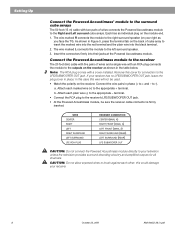
... wiring, which can result in -wall installation. The supplied cables are not intended for in electrical shock or damage to your system. Check local building codes or enlist a qualified installer. Connect the Powered Acoustimass module to the center and front cube arrays Three individual 20...cube array to the center speaker. Figure 4 Separating cables Figure 5 Making cube speaker connections CAUTION: Before making any connections turn off your receiver. Setting Up Connect the speakers Connect the cube arrays to the Powered Acoustimass® module, and then connect the module to ...
... wiring, which can result in -wall installation. The supplied cables are not intended for in electrical shock or damage to your system. Check local building codes or enlist a qualified installer. Connect the Powered Acoustimass module to the center and front cube arrays Three individual 20...cube array to the center speaker. Figure 4 Separating cables Figure 5 Making cube speaker connections CAUTION: Before making any connections turn off your receiver. Setting Up Connect the speakers Connect the cube arrays to the Powered Acoustimass® module, and then connect the module to ...
Owner's guide
Page 10
... Connect the RCA plug to the left surround speaker. 3. Setting Up Connect the Powered Acoustimass® module to the surround cube arrays The 50 foot (15 m) cable with two pairs of wires connects the Powered Acoustimass module to -). to the Right and Left surround cube arrays. Attach each plain wire... receiver as you face the TV). Insert the connectors firmly into the black terminal. 2. Connect the Powered Acoustimass module to the receiver The 20 foot (6m) cable with five pairs of wires and a single wire with a cover installed. Remove this could damage your television...
... Connect the RCA plug to the left surround speaker. 3. Setting Up Connect the Powered Acoustimass® module to the surround cube arrays The 50 foot (15 m) cable with two pairs of wires connects the Powered Acoustimass module to -). to the Right and Left surround cube arrays. Attach each plain wire... receiver as you face the TV). Insert the connectors firmly into the black terminal. 2. Connect the Powered Acoustimass module to the receiver The 20 foot (6m) cable with five pairs of wires and a single wire with a cover installed. Remove this could damage your television...
Owner's guide
Page 13
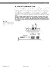
See Figure 9. You may be sure that has unique, "square" cable ends. Using Your Acoustimass® 15 Speakers Figure 9 Use either the optical or coaxial digital sound cables and connections for specific details. You must select digital audio. You must also be sure to set up the digital signal using the receiver's front ...
See Figure 9. You may be sure that has unique, "square" cable ends. Using Your Acoustimass® 15 Speakers Figure 9 Use either the optical or coaxial digital sound cables and connections for specific details. You must select digital audio. You must also be sure to set up the digital signal using the receiver's front ...

Owner's guide
Page 14
... (video, CD, DVD, tuner). • Check the speaker connections. • Turn the Powered Acoustimass module ON. • For digital sound, be sure a coaxial or optical cable connects the digital output of this guide. Please note that the settings are correct (+ to + and...• Reduce the volume of your Acoustimass 15 speaker system may be cleaned with your Acoustimass 15 speakers, turn off your sound source and try the solutions below. Maintaining Your Acoustimass® 15 Speakers Troubleshooting If you have a problem, contact your Bose® dealer to arrange for service....
... (video, CD, DVD, tuner). • Check the speaker connections. • Turn the Powered Acoustimass module ON. • For digital sound, be sure a coaxial or optical cable connects the digital output of this guide. Please note that the settings are correct (+ to + and...• Reduce the volume of your Acoustimass 15 speaker system may be cleaned with your Acoustimass 15 speakers, turn off your sound source and try the solutions below. Maintaining Your Acoustimass® 15 Speakers Troubleshooting If you have a problem, contact your Bose® dealer to arrange for service....
Owner's guide
Page 15
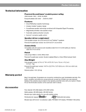
... x 19.0 cm x 59.0 cm) 33 lb (15 kg) Packed system: 53 lb (24 kg) Warranty period Bose® Acoustimass 15 speakers are covered by a limited five-year transferable warranty. Accessories Floor stands: UFS-20B (black), UFS-20W (white) Wall brackets: UB-20B (black), UB-20W (white) Module input cable adapter for use with your system...
... x 19.0 cm x 59.0 cm) 33 lb (15 kg) Packed system: 53 lb (24 kg) Warranty period Bose® Acoustimass 15 speakers are covered by a limited five-year transferable warranty. Accessories Floor stands: UFS-20B (black), UFS-20W (white) Wall brackets: UB-20B (black), UB-20W (white) Module input cable adapter for use with your system...

