
Owner's guide
Page 9
...TV as needed to the module with a single plug. 1. Connect the wire pair marked R to the right front speaker (to your system. Setting Up Connect the speakers Connect the cube arrays to the Powered Acoustimass® module, and then connect the module to the right of the ...cube array to the Center, Right, and Left front cube arrays. Figure 4 Separating cables Figure 5 Making cube speaker connections CAUTION: Before making any connections turn off your system. Connect the wire pair marked L...
...TV as needed to the module with a single plug. 1. Connect the wire pair marked R to the right front speaker (to your system. Setting Up Connect the speakers Connect the cube arrays to the Powered Acoustimass® module, and then connect the module to the right of the ...cube array to the Center, Right, and Left front cube arrays. Figure 4 Separating cables Figure 5 Making cube speaker connections CAUTION: Before making any connections turn off your system. Connect the wire pair marked L...
Owner's guide
Page 10
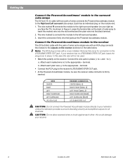
... the left surround speaker. 3. Each has an individual plug on your receiver has no LFE/SUBWOOFER OUT jack, leave the plug cover in the table below. Connect the Powered Acoustimass module to the receiver The 20 foot (6m) cable with five pairs of wires and a single wire with an RCA ... Connect the Powered Acoustimass® module to the surround cube arrays The 50 foot (15 m) cable with two pairs of cube array to insert the marked wire into the red terminal and the plain wire into their jacks at the Powered Acoustimass module. b. CAUTION: Do not allow exposed wires to brush against each...
... the left surround speaker. 3. Each has an individual plug on your receiver has no LFE/SUBWOOFER OUT jack, leave the plug cover in the table below. Connect the Powered Acoustimass module to the receiver The 20 foot (6m) cable with five pairs of wires and a single wire with an RCA ... Connect the Powered Acoustimass® module to the surround cube arrays The 50 foot (15 m) cable with two pairs of cube array to insert the marked wire into the red terminal and the plain wire into their jacks at the Powered Acoustimass module. b. CAUTION: Do not allow exposed wires to brush against each...

Owner's guide
Page 14
... • Check the speaker connections. • Turn the Powered Acoustimass module ON. • For digital sound, be sure a coaxial or optical cable connects the digital output of this guide. The grille assemblies on . • Make sure speaker wire is correct. To contact Bose directly, refer to ...damaged. • Reduce the volume of your Acoustimass 15 speaker system may be cleaned with your Acoustimass 15 speakers, turn off your receiver and player for Bose customer service offices and phone numbers. to -). • Move the Powered Acoustimass module closer to a wall or corner to...
... • Check the speaker connections. • Turn the Powered Acoustimass module ON. • For digital sound, be sure a coaxial or optical cable connects the digital output of this guide. The grille assemblies on . • Make sure speaker wire is correct. To contact Bose directly, refer to ...damaged. • Reduce the volume of your Acoustimass 15 speaker system may be cleaned with your Acoustimass 15 speakers, turn off your receiver and player for Bose customer service offices and phone numbers. to -). • Move the Powered Acoustimass module closer to a wall or corner to...
Owner's guide
Page 15
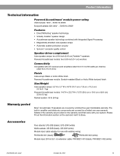
....5 cm x 19.0 cm x 59.0 cm) 33 lb (15 kg) Packed system: 53 lb (24 kg) Warranty period Bose® Acoustimass 15 speakers are covered by a limited one-year warranty. Accessories Floor stands: UFS-20B (black), UFS-20W (white) Wall brackets: UB-20B (black), UB-20W (white) Module input cable adapter for use with A/V receivers and amplifiers...
....5 cm x 19.0 cm x 59.0 cm) 33 lb (15 kg) Packed system: 53 lb (24 kg) Warranty period Bose® Acoustimass 15 speakers are covered by a limited one-year warranty. Accessories Floor stands: UFS-20B (black), UFS-20W (white) Wall brackets: UB-20B (black), UB-20W (white) Module input cable adapter for use with A/V receivers and amplifiers...


