Instruction Manual
Page 1
LTC 5136 Series Instruction Manual EN AutoDome® Controller
LTC 5136 Series Instruction Manual EN AutoDome® Controller
Instruction Manual
Page 2
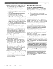
... product. Alternately, this unit on or pinched by the manufacturer. When installing an outdoor system, extreme care should be walked on an unstable stand, tripod, bracket, or mount. U.S.A. LTC 5136 Series | Instruction Manual | Important Safeguards EN | 2 Important Safeguards 1. Follow Instructions - This plug will fit into a grounding-type power outlet. This is a safety feature. Overloading - This unit should be equipped...
... product. Alternately, this unit on or pinched by the manufacturer. When installing an outdoor system, extreme care should be walked on an unstable stand, tripod, bracket, or mount. U.S.A. LTC 5136 Series | Instruction Manual | Important Safeguards EN | 2 Important Safeguards 1. Follow Instructions - This plug will fit into a grounding-type power outlet. This is a safety feature. Overloading - This unit should be equipped...
Instruction Manual
Page 3
... outside cable system is connected to radio communications. and Canadian Models Only) This device complies with the instruction manual, may cause undesired operation. This equipment generates, uses and radiates radio frequency energy, and if not installed and used replacement parts specified by following two conditions: (1) This device may not cause harmful interference, and (2) This device must accept any service or repairs to this...
... outside cable system is connected to radio communications. and Canadian Models Only) This device complies with the instruction manual, may cause undesired operation. This equipment generates, uses and radiates radio frequency energy, and if not installed and used replacement parts specified by following two conditions: (1) This device may not cause harmful interference, and (2) This device must accept any service or repairs to this...
Instruction Manual
Page 8
LTC 5136 Series | Instruction Manual | Contents EN | 8 Table of Contents Important Safeguards 2 FCC Information 2 1 UNPACKING 9 2 SERVICE 9 3 DESCRIPTION 9 3.1 Power 9 4 INSTALLATION 10 4.1 General 10 4.2 Installation using Biphase Code 10 4.3 Installation using RS-232 Data Direct to Camera Site 11 4.4 Installation using an RS-232 Data Transmission Link to a Biphase Camera Site 12 4.5 AutoDome Camera or Receiver/Driver Site Configuration 13 5 SETTING FAST ADDRESS FEATURE 13 6 CONTROLLER OPERATION 14 6.1 Controls/Indicators 14 7 TECHNICAL REFERENCE 16 8 DATA CONVERTER PINOUTS...
LTC 5136 Series | Instruction Manual | Contents EN | 8 Table of Contents Important Safeguards 2 FCC Information 2 1 UNPACKING 9 2 SERVICE 9 3 DESCRIPTION 9 3.1 Power 9 4 INSTALLATION 10 4.1 General 10 4.2 Installation using Biphase Code 10 4.3 Installation using RS-232 Data Direct to Camera Site 11 4.4 Installation using an RS-232 Data Transmission Link to a Biphase Camera Site 12 4.5 AutoDome Camera or Receiver/Driver Site Configuration 13 5 SETTING FAST ADDRESS FEATURE 13 6 CONTROLLER OPERATION 14 6.1 Controls/Indicators 14 7 TECHNICAL REFERENCE 16 8 DATA CONVERTER PINOUTS...
Instruction Manual
Page 9
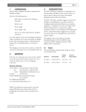
... Allegiant receiver/driver functions including variable speed pan/tilt/zoom, pre-positions, auxiliaries, etc. Bosch Security Systems | 04 September 2003 Sales Representative or Customer Service. Model No. Rated Voltage Voltage Range Power at Rated Voltage LTC 5136/51 230 VAC, 50/60 Hz 195.5 to 253 6 W LTC 5136/61 120 VAC, 50/60 Hz 105 to return and shipping instructions. 3 DESCRIPTION The LTC 5136 Series Controllers are designed...
... Allegiant receiver/driver functions including variable speed pan/tilt/zoom, pre-positions, auxiliaries, etc. Bosch Security Systems | 04 September 2003 Sales Representative or Customer Service. Model No. Rated Voltage Voltage Range Power at Rated Voltage LTC 5136/51 230 VAC, 50/60 Hz 195.5 to 253 6 W LTC 5136/61 120 VAC, 50/60 Hz 105 to return and shipping instructions. 3 DESCRIPTION The LTC 5136 Series Controllers are designed...
Instruction Manual
Page 10
... biphase control code outputs of the power supply cable into biphase control code. All other video processing equipment (switcher, multiplexer, etc.). Three installation sections are no video connections to the Controller unit. The orientation is connected. LTC 5136 Series | Instruction Manual | Installation EN | 10 4 INSTALLATION 4.1 General The desktop Controller unit should have the terminating resistor removed when the looping cable is not important -- In most applications, the supplied 3 m (10 ft) power/data...
... biphase control code outputs of the power supply cable into biphase control code. All other video processing equipment (switcher, multiplexer, etc.). Three installation sections are no video connections to the Controller unit. The orientation is connected. LTC 5136 Series | Instruction Manual | Installation EN | 10 4 INSTALLATION 4.1 General The desktop Controller unit should have the terminating resistor removed when the looping cable is not important -- In most applications, the supplied 3 m (10 ft) power/data...
Instruction Manual
Page 11
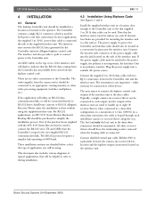
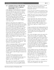
... receiver/driver location. If the power supply cable must be set (via internal DIP switch or on the side of the power supply cable into a suitable AC power source. Connect the bayonet style connector of the junction box. the Interface Unit is not important; Bosch Security Systems | 04 September 2003 LTC 5136 Series | Instruction Manual | Installation EN | 11 Pin 1 Pin 6 Figure 1 Interface Unit Supplied with LTC 5136 The removable...
... receiver/driver location. If the power supply cable must be set (via internal DIP switch or on the side of the power supply cable into a suitable AC power source. Connect the bayonet style connector of the junction box. the Interface Unit is not important; Bosch Security Systems | 04 September 2003 LTC 5136 Series | Instruction Manual | Installation EN | 11 Pin 1 Pin 6 Figure 1 Interface Unit Supplied with LTC 5136 The removable...
Instruction Manual
Page 12
... by the Controller is much over 20-30 m (60-90 ft), the use of the interface unit to the data cable. Bosch Security Systems | 04 September 2003 LTC 5136 Series | Instruction Manual | Installation EN | 12 4.4 Installation Using an RS-232 Data Transmission Link to a Biphase Camera Site (See Figure 6) In this application, the RS-232 data that the supplied 3 m (10 ft) data cable can easily be connected to the...
... by the Controller is much over 20-30 m (60-90 ft), the use of the interface unit to the data cable. Bosch Security Systems | 04 September 2003 LTC 5136 Series | Instruction Manual | Installation EN | 12 4.4 Installation Using an RS-232 Data Transmission Link to a Biphase Camera Site (See Figure 6) In this application, the RS-232 data that the supplied 3 m (10 ft) data cable can easily be connected to the...
Instruction Manual
Page 13
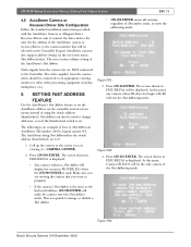
... you want to the Controller. Press ON-636-ENTER. Bosch Security Systems | 04 September 2003 Figure FA3 Fast Address can also be selected on the Controller keypad. LTC 5136 Series | Instruction Manual | Setting Fast Addess Feature EN | 13 4.5 AutoDome Camera or Receiver/Driver Site Configuration Follow the standard installation instructions provided with 26 will exit the Fast Addressing mode. AutoDome cameras also support address setting via the controller and on -screen menu Fast Address feature. Press ON...
... you want to the Controller. Press ON-636-ENTER. Bosch Security Systems | 04 September 2003 Figure FA3 Fast Address can also be selected on the Controller keypad. LTC 5136 Series | Instruction Manual | Setting Fast Addess Feature EN | 13 4.5 AutoDome Camera or Receiver/Driver Site Configuration Follow the standard installation instructions provided with 26 will exit the Fast Addressing mode. AutoDome cameras also support address setting via the controller and on -screen menu Fast Address feature. Press ON...
Instruction Manual
Page 14
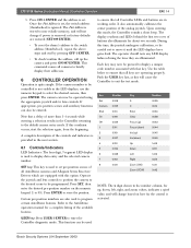
...: The x digit shown in the Controller returning to display a unique code number associated with this time, the joystick undergoes calibration, so be operated using the appropriate joystick and/or lens controls. If this mode, the Controller sounds a short beep. SET key: This key is used to briefly display their addresses. 6 CONTROLLER OPERATION Operation is removed or factory defaults are operating properly. Certain pre-position numbers are also used to set . It also automatically calibrates the center position of buttons also illuminate...
...: The x digit shown in the Controller returning to display a unique code number associated with this time, the joystick undergoes calibration, so be operated using the appropriate joystick and/or lens controls. If this mode, the Controller sounds a short beep. SET key: This key is used to briefly display their addresses. 6 CONTROLLER OPERATION Operation is removed or factory defaults are operating properly. Certain pre-position numbers are also used to set . It also automatically calibrates the center position of buttons also illuminate...
Instruction Manual
Page 15
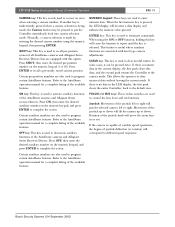
LTC 5136 Series | Instruction Manual | Controller Operation EN | 15 CAMERA key: This key is used to terminate commands. SHOT key: This key is used to correct an error when selecting a camera number. ENTER key: This key is only used to the default state. CLEAR key: This key is numeric data in the camera display, the first push clears this key will move the zoom lens in the LED display, the first push clears the entire Controller, back to deactivate auxiliary...
LTC 5136 Series | Instruction Manual | Controller Operation EN | 15 CAMERA key: This key is used to terminate commands. SHOT key: This key is used to correct an error when selecting a camera number. ENTER key: This key is only used to the default state. CLEAR key: This key is numeric data in the camera display, the first push clears this key will move the zoom lens in the LED display, the first push clears the entire Controller, back to deactivate auxiliary...
Instruction Manual
Page 16
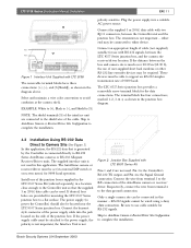
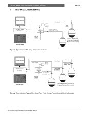
LTC 5136 Series | Instruction Manual | Technical Reference 7 TECHNICAL REFERENCE EN | 16 Video Monitor DVR or Video Switcher Data Converter Unit Power Supply Adapter Video Signal Up to 16 biphase control code outputs RS-232 Data & Power Controller Figure 3 Typical Camera Site Using Biphase Control Code Video Signal Typical AutoDome Cameras or Allegiant Receiver/Driver units Video Monitor DVR or Video Switcher Controller Video Signal Power Supply Adapter Data Converter Unit Typical biphase control code output RS-232 Data & Power Video Signal Daisy Chain Biphase Data Video ...
LTC 5136 Series | Instruction Manual | Technical Reference 7 TECHNICAL REFERENCE EN | 16 Video Monitor DVR or Video Switcher Data Converter Unit Power Supply Adapter Video Signal Up to 16 biphase control code outputs RS-232 Data & Power Controller Figure 3 Typical Camera Site Using Biphase Control Code Video Signal Typical AutoDome Cameras or Allegiant Receiver/Driver units Video Monitor DVR or Video Switcher Controller Video Signal Power Supply Adapter Data Converter Unit Typical biphase control code output RS-232 Data & Power Video Signal Daisy Chain Biphase Data Video ...
Instruction Manual
Page 17
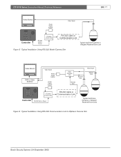
LTC 5136 Series | Instruction Manual | Technical Reference EN | 17 Video Monitor Power Supply Adapter Video Signal Controller RS-232 Data & Power LTC 8557 Junction Box RS-232 Cable or Communication Link Typical AutoDome Camera or Allegiant Receiver/Driver unit Figure 5 Typical Installation Using RS-232 Model Camera Site Video Monitor DVR or Video Switcher Video Signal Power Supply Adapter Power Supply Adapter Data Converter Unit Biphase Data RS-232 Data Video Signal Biphase Data LTC 8557 Junction Box Controller RS-232 Data & Power RS-232 Cable or...
LTC 5136 Series | Instruction Manual | Technical Reference EN | 17 Video Monitor Power Supply Adapter Video Signal Controller RS-232 Data & Power LTC 8557 Junction Box RS-232 Cable or Communication Link Typical AutoDome Camera or Allegiant Receiver/Driver unit Figure 5 Typical Installation Using RS-232 Model Camera Site Video Monitor DVR or Video Switcher Video Signal Power Supply Adapter Power Supply Adapter Data Converter Unit Biphase Data RS-232 Data Video Signal Biphase Data LTC 8557 Junction Box Controller RS-232 Data & Power RS-232 Cable or...
Instruction Manual
Page 18
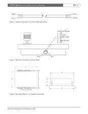
Rx (Not used 3. LTC 5136 Series | Instruction Manual | Technical Reference Pin 6 Pin 1 Figure 7 Supplied 6-Conductor 3 m (10 ft) Data Cable Detail EN | 18 Pin 1 Pin 6 Connector Pinouts: 1. 12V 2. Signal Ground 6. 12V Pin 6 Figure 8 Rear Panel Controller Connector Detail Pin 1 154 6.08 108 122 4.26 4.80 38 1 .5 70 2.75 mm in Figure 9 Mounting Dimensions of Supplied Interface Box 127 5.0 132 mm 5.2 in Bosch Security Systems | 04 September 2003 Tx 5. Not used ) 4.
Rx (Not used 3. LTC 5136 Series | Instruction Manual | Technical Reference Pin 6 Pin 1 Figure 7 Supplied 6-Conductor 3 m (10 ft) Data Cable Detail EN | 18 Pin 1 Pin 6 Connector Pinouts: 1. 12V 2. Signal Ground 6. 12V Pin 6 Figure 8 Rear Panel Controller Connector Detail Pin 1 154 6.08 108 122 4.26 4.80 38 1 .5 70 2.75 mm in Figure 9 Mounting Dimensions of Supplied Interface Box 127 5.0 132 mm 5.2 in Bosch Security Systems | 04 September 2003 Tx 5. Not used ) 4.
Instruction Manual
Page 19
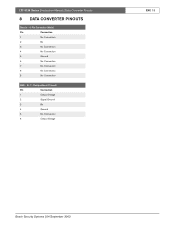
RJ-11 Designations (If Used) Pin Connection 1 Output Voltage 2 Signal Ground 3 Rx 4 Ground 5 No Connection 6 Output Voltage EN | 19 Bosch Security Systems | 04 September 2003 LTC 5136 Series | Instruction Manual | Data Converter Pinouts 8 DATA CONVERTER PINOUTS Data In - 9-Pin Connector (Male) Pin Connection 1 No Connection 2 Rx 3 No Connection 4 No Connection 5 Ground 6 No Connection 7 No Connection 8 No Connection 9 No Connection KBD -
RJ-11 Designations (If Used) Pin Connection 1 Output Voltage 2 Signal Ground 3 Rx 4 Ground 5 No Connection 6 Output Voltage EN | 19 Bosch Security Systems | 04 September 2003 LTC 5136 Series | Instruction Manual | Data Converter Pinouts 8 DATA CONVERTER PINOUTS Data In - 9-Pin Connector (Male) Pin Connection 1 No Connection 2 Rx 3 No Connection 4 No Connection 5 Ground 6 No Connection 7 No Connection 8 No Connection 9 No Connection KBD -

Instruction Manual
Page 20
P.O. Box 80002 5600 JB Eindhoven The Netherlands Tele +31 40 27 80000 © 2003 Bosch Security Systems GmbH 3935 890 06114 03-37 | September 11, 2003 | Data subject to change without notice. Bosch Security Systems, Inc. 850 Greenfield Road Lancaster, PA 17601 EE.UU. Tel: 800-326-3270 Fax: 1-717-735-6560 www.boschsecuritysystems.com Robert Bosch GmbH Geschäftsbereich Postfach 10 60 50 70049 Stuttgart Telefax (0711) 8 11-12 34 Bosch Security Systems B.V.
P.O. Box 80002 5600 JB Eindhoven The Netherlands Tele +31 40 27 80000 © 2003 Bosch Security Systems GmbH 3935 890 06114 03-37 | September 11, 2003 | Data subject to change without notice. Bosch Security Systems, Inc. 850 Greenfield Road Lancaster, PA 17601 EE.UU. Tel: 800-326-3270 Fax: 1-717-735-6560 www.boschsecuritysystems.com Robert Bosch GmbH Geschäftsbereich Postfach 10 60 50 70049 Stuttgart Telefax (0711) 8 11-12 34 Bosch Security Systems B.V.


