

Installation Instructions
Page 3
Other required accessories from specialist outlets 17 4. Contents Before you Begin 5 Definitions 5 Important information 5 Installation options 6 Individual unit 6 SideĆbyĆSide 6 Individual appliances with partition 6 At the end of the kitchen units 6 Installation location 7 Installation room 7 Installation cavity 7 Furniture/fixtures 7 Base 7 Connecting the power 8 Additional grounding procedure 8 Grounding ...
Other required accessories from specialist outlets 17 4. Contents Before you Begin 5 Definitions 5 Important information 5 Installation options 6 Individual unit 6 SideĆbyĆSide 6 Individual appliances with partition 6 At the end of the kitchen units 6 Installation location 7 Installation room 7 Installation cavity 7 Furniture/fixtures 7 Base 7 Connecting the power 8 Additional grounding procedure 8 Grounding ...
Installation Instructions
Page 4
... 25 12. Preparing the furniture doors 31 19. Mounting of the appliance 18 3. Installation instructions 18 1. Attaching an alternative antiĆtip device 24 8. Attaching the appliance to the appliance 28 16. Commissioning the Appliance 30 18. Shorten the finger guard 36 24. Changing the door ...30. Connecting the water to the top of the cavity 28 15. Attaching the covers 37 26. Preparing the appliance 19 5. Attaching the edge protection 25 10.SideĆbyĆSide installation 25 11. Preparing the installation cavity 22 7. Loading...
... 25 12. Preparing the furniture doors 31 19. Mounting of the appliance 18 3. Installation instructions 18 1. Attaching an alternative antiĆtip device 24 8. Attaching the appliance to the appliance 28 16. Commissioning the Appliance 30 18. Shorten the finger guard 36 24. Changing the door ...30. Connecting the water to the top of the cavity 28 15. Attaching the covers 37 26. Preparing the appliance 19 5. Attaching the edge protection 25 10.SideĆbyĆSide installation 25 11. Preparing the installation cavity 22 7. Loading...
Installation Instructions
Page 5
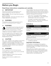
... the Canadian Electric Code C22.1 - Important information The importance of not observing this appliance only for warranty information. e WARNING This appliance must observe. e WARNING These appliances are intended for local inspector's use by a qualified fitter. This indicates that death... Observe all regulations and instructions in accordance with local codes and ordinances and be emphasised enough. In the U.S.A., in this appliance requires basic mechanical, carpentry and plumbing skills. Level ć Installation of a local code: - Definitions d WARNING d ...
... the Canadian Electric Code C22.1 - Important information The importance of not observing this appliance only for warranty information. e WARNING This appliance must observe. e WARNING These appliances are intended for local inspector's use by a qualified fitter. This indicates that death... Observe all regulations and instructions in accordance with local codes and ordinances and be emphasised enough. In the U.S.A., in this appliance requires basic mechanical, carpentry and plumbing skills. Level ć Installation of a local code: - Definitions d WARNING d ...
Installation Instructions
Page 6
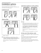
... doors are installed SideĆbyĆSide, the Basic Combination SideĆby the design of the kitchen and the function of the appliance is visible, a side panel must be connected firmly to the wall, the floor and overhead furniture/fixtures before the... square and the exact size. 6 Use the Extreme Combination SideĆby ĆSide * * * Partition required! Individual unit Individual appliances with partition 1. 2. See the section on Optional accessories" on page 17. - The dimensions of the partition 5/8" (16 mm). See the section on Optional accessories" on...
... doors are installed SideĆbyĆSide, the Basic Combination SideĆby the design of the kitchen and the function of the appliance is visible, a side panel must be connected firmly to the wall, the floor and overhead furniture/fixtures before the... square and the exact size. 6 Use the Extreme Combination SideĆby ĆSide * * * Partition required! Individual unit Individual appliances with partition 1. 2. See the section on Optional accessories" on page 17. - The dimensions of the partition 5/8" (16 mm). See the section on Optional accessories" on...

Installation Instructions
Page 7
...to a heat source is screwed securely to observe the specified dimensions of the installation cavity for a troubleĆfree installation of the appliance and for the loadĆbearing capacity at risk of the furniture front. spirit level, diagonal measurements, etc. For this reason it ... made of the room. The installation area must be flush. Squareness can be flat and level. Base d WARNING d A fullyĆload appliance is very heavy ć for the subsequent general view of frost. in doubt, contact an architect or a building expert. 7 The installation location...
...to a heat source is screwed securely to observe the specified dimensions of the installation cavity for a troubleĆfree installation of the appliance and for the loadĆbearing capacity at risk of the furniture front. spirit level, diagonal measurements, etc. For this reason it ... made of the room. The installation area must be flush. Squareness can be flat and level. Base d WARNING d A fullyĆload appliance is very heavy ć for the subsequent general view of frost. in doubt, contact an architect or a building expert. 7 The installation location...
Installation Instructions
Page 8
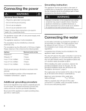
... water connection, observe the permitted installation areas for the electric current. Failure to follow these instructions can be behind the appliance. The receptacle must be installed by a licensed electrician only. The installation must be between 25 and 120 p.s.i. (1.72...installation areas and dimensions see "Installation dimensions", page 8. Connecting the power2. Maximum outer diameter of the automatic ice maker. The appliance comes with local plumbing regulations. A separate shutĆoff valve for operation of the water pipe (without fittings): 13/32"...
... water connection, observe the permitted installation areas for the electric current. Failure to follow these instructions can be behind the appliance. The receptacle must be installed by a licensed electrician only. The installation must be between 25 and 120 p.s.i. (1.72...installation areas and dimensions see "Installation dimensions", page 8. Connecting the power2. Maximum outer diameter of the automatic ice maker. The appliance comes with local plumbing regulations. A separate shutĆoff valve for operation of the water pipe (without fittings): 13/32"...
Installation Instructions
Page 9
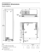
Single installation6. Side wall of niche, depending on kitchen design (see DESIGN GUIDE) D = 24" (610 mm) minimum NOTE: Cavity must be suare. Legend: A Area for installation of the water connection B Area for installation of the power connection D Opening depth of the cavity must be flush. Installation dimensions5. Appliance 18" 24" 30" X 18" (457 mm) 24 (610 mm) 30" (762 mm) Y 9" (229 mm) 12" (305 mm) 15" (381 mm) 9
Single installation6. Side wall of niche, depending on kitchen design (see DESIGN GUIDE) D = 24" (610 mm) minimum NOTE: Cavity must be suare. Legend: A Area for installation of the water connection B Area for installation of the power connection D Opening depth of the cavity must be flush. Installation dimensions5. Appliance 18" 24" 30" X 18" (457 mm) 24 (610 mm) 30" (762 mm) Y 9" (229 mm) 12" (305 mm) 15" (381 mm) 9
Installation Instructions
Page 10
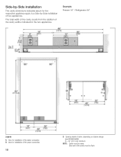
... from the addition of the cavity widths indicated for installation of the power connection 10 D Opening depth of the water connection B Area for the two appliances. Example: Freezer 18" / Refrigerator 30" Legend: A Area for installation of niche, depending on kitchen design (see DESIGN GUIDE) D = 24" ...(610 mm) minimum NOTE: Cavity must be suare. Side wall of two appliances. SideĆbyĆSide installation The cavity dimensions indicated above for the respective appliance apply to a SideĆbyĆSide installation of the cavity must be flush.
... from the addition of the cavity widths indicated for installation of the power connection 10 D Opening depth of the water connection B Area for the two appliances. Example: Freezer 18" / Refrigerator 30" Legend: A Area for installation of niche, depending on kitchen design (see DESIGN GUIDE) D = 24" ...(610 mm) minimum NOTE: Cavity must be suare. Side wall of two appliances. SideĆbyĆSide installation The cavity dimensions indicated above for the respective appliance apply to a SideĆbyĆSide installation of the cavity must be flush.

Installation Instructions
Page 12
d) This dimension may vary. b) Dimensions may vary depending on installation, panel thickness and kitchen hardware. 12 e) Unit dimensions Note: One design of door panel may vary. For further information about the different styles check the DESIGN GUIDE. c) Thickness of the wooden panel displayed. Appliance dimensions7. 1. 18" Appliance (Freezer/Freezer with Ice and Water dispenser) e) e) Front view (without door panel) Legend: a) Adjustment in levelling legs +13/8" (35 mm) / -1/2" (13 mm).
d) This dimension may vary. b) Dimensions may vary depending on installation, panel thickness and kitchen hardware. 12 e) Unit dimensions Note: One design of door panel may vary. For further information about the different styles check the DESIGN GUIDE. c) Thickness of the wooden panel displayed. Appliance dimensions7. 1. 18" Appliance (Freezer/Freezer with Ice and Water dispenser) e) e) Front view (without door panel) Legend: a) Adjustment in levelling legs +13/8" (35 mm) / -1/2" (13 mm).
Installation Instructions
Page 13
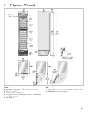
2. 18" Appliance (Wine unit) e) e) Front view (without door panel) Legend: a) Adjustment in levelling legs +13/8" (35 mm) / -1/2" (13 mm). e) Unit dimensions Note: One design of door panel may vary depending on installation, panel thickness and kitchen hardware. c) Thickness of the wooden panel displayed. d) This dimension may vary. For further information about the different styles check the DESIGN GUIDE. 13 b) Dimensions may vary.
2. 18" Appliance (Wine unit) e) e) Front view (without door panel) Legend: a) Adjustment in levelling legs +13/8" (35 mm) / -1/2" (13 mm). e) Unit dimensions Note: One design of door panel may vary depending on installation, panel thickness and kitchen hardware. c) Thickness of the wooden panel displayed. d) This dimension may vary. For further information about the different styles check the DESIGN GUIDE. 13 b) Dimensions may vary.
Installation Instructions
Page 14
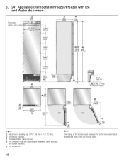
3. 24" Appliance (Refrigerator/Freezer/Freezer with Ice and Water dispenser) e) e) Front view (without door panel) Legend: a) Adjustment in levelling legs +13/8" (35 mm) / -1/2" (13 mm). e) Unit dimensions 14 Note: One design of door panel may vary. For further information about the different styles check the DESIGN GUIDE. c) Thickness of the wooden panel displayed. d) This dimension may vary. b) Dimensions may vary depending on installation, panel thickness and kitchen hardware.
3. 24" Appliance (Refrigerator/Freezer/Freezer with Ice and Water dispenser) e) e) Front view (without door panel) Legend: a) Adjustment in levelling legs +13/8" (35 mm) / -1/2" (13 mm). e) Unit dimensions 14 Note: One design of door panel may vary. For further information about the different styles check the DESIGN GUIDE. c) Thickness of the wooden panel displayed. d) This dimension may vary. b) Dimensions may vary depending on installation, panel thickness and kitchen hardware.

Installation Instructions
Page 15
c) Thickness of the wooden panel displayed. e) Unit dimensions Note: One design of door panel may vary. b) Dimensions may vary depending on installation, panel thickness and kitchen hardware. d) This dimension may vary. For further information about the different styles check the DESIGN GUIDE. 15 4. 24" Appliance (Wine unit) e) e) Front view (without door panel) Legend: a) Adjustment in levelling legs +13/8" (35 mm) / -1/2" (13 mm).
c) Thickness of the wooden panel displayed. e) Unit dimensions Note: One design of door panel may vary. b) Dimensions may vary depending on installation, panel thickness and kitchen hardware. d) This dimension may vary. For further information about the different styles check the DESIGN GUIDE. 15 4. 24" Appliance (Wine unit) e) e) Front view (without door panel) Legend: a) Adjustment in levelling legs +13/8" (35 mm) / -1/2" (13 mm).
Installation Instructions
Page 16
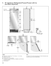
5. 30" Appliance (Refrigerator/Freezer/Freezer with Ice and Water dispenser) e) e) Front view (without door panel) Legend: a) Adjustment in levelling legs +13/8" (35 mm) / -1/2" (13 mm). e) Unit dimensions 16 Note: One design of door panel may vary. b) Dimensions may vary depending on installation, panel thickness and kitchen hardware. d) This dimension may vary. c) Thickness of the wooden panel displayed. For further information about the different styles check the DESIGN GUIDE.
5. 30" Appliance (Refrigerator/Freezer/Freezer with Ice and Water dispenser) e) e) Front view (without door panel) Legend: a) Adjustment in levelling legs +13/8" (35 mm) / -1/2" (13 mm). e) Unit dimensions 16 Note: One design of door panel may vary. b) Dimensions may vary depending on installation, panel thickness and kitchen hardware. d) This dimension may vary. c) Thickness of the wooden panel displayed. For further information about the different styles check the DESIGN GUIDE.
Installation Instructions
Page 17
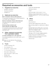
...;by ĆSide Sealing kit For permanent connection of the installation cavity - MarkingĆout level, length at least 4' (1.2 m) for individual appliances or 7' (2.0 m) for standard height furniture doors without fittings): 13/32" (10 mm). - Other - Dolly, hand truck - Suitable material...- Basic Combination SideĆby ĆSide installation 5. Extreme Combination SideĆbyĆSide Heating kit If the gap between the appliances is less than 6" (160 mm). Other required accessories from damage (e.g. for covering and protecting furniture (e.g. i Maximum outer diameter of ...
...;by ĆSide Sealing kit For permanent connection of the installation cavity - MarkingĆout level, length at least 4' (1.2 m) for individual appliances or 7' (2.0 m) for standard height furniture doors without fittings): 13/32" (10 mm). - Other - Dolly, hand truck - Suitable material...- Basic Combination SideĆby ĆSide installation 5. Extreme Combination SideĆbyĆSide Heating kit If the gap between the appliances is less than 6" (160 mm). Other required accessories from damage (e.g. for covering and protecting furniture (e.g. i Maximum outer diameter of ...
Installation Instructions
Page 18
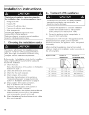
...All furniture parts in the vicinity of the adjacent furniture/fixtures. q Check location of your appliance. Installation instructions d CAUTION d The following table: Appliance width Erection via appliance rear Erection via appliance side panel 18" / 457 mm 24" / 610 mm 30" / 762 mm 36...mm 911/4" / 2315 mm 18 q Check that the installation cavity complies with all requirements for individual appliance types. 1. If the appliance cannot be transported horizontally. Also follow the instructions in an upright position due to the following installation instructions...
...All furniture parts in the vicinity of the adjacent furniture/fixtures. q Check location of your appliance. Installation instructions d CAUTION d The following table: Appliance width Erection via appliance rear Erection via appliance side panel 18" / 457 mm 24" / 610 mm 30" / 762 mm 36...mm 911/4" / 2315 mm 18 q Check that the installation cavity complies with all requirements for individual appliance types. 1. If the appliance cannot be transported horizontally. Also follow the instructions in an upright position due to the following installation instructions...
Installation Instructions
Page 19
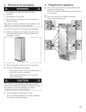
...hand truck securely. If in front of carpet, lino, etc. to protect the surface of packaging. q Move the appliance with adhesive tape in doubt, contact your dealer. 19 d CAUTION d Do not remove transportation safety devices which attach the furniture fronts....careful, otherwise people who are helping may be injured or the appliance may get lost. Remove the cartoon. The appliance is visibly damaged. q Check appliance for damage in suitable receptacles, otherwise they may be damaged. The appliance may tip forwards. To protect the base from damage during ...
...hand truck securely. If in front of carpet, lino, etc. to protect the surface of packaging. q Move the appliance with adhesive tape in doubt, contact your dealer. 19 d CAUTION d Do not remove transportation safety devices which attach the furniture fronts....careful, otherwise people who are helping may be injured or the appliance may get lost. Remove the cartoon. The appliance is visibly damaged. q Check appliance for damage in suitable receptacles, otherwise they may be damaged. The appliance may tip forwards. To protect the base from damage during ...
Installation Instructions
Page 21
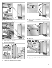
q Fit the plastic part of the grill. q Span the spring on the appliance. q Change over the fixation parts on the door. q Fix the hinges on the hinge. Tighten the screw from 0 to I. 21 Change the hinges crosswise! q Change over the hinge angle. q Mount the grill completely. q Fix the door.
q Fit the plastic part of the grill. q Span the spring on the appliance. q Change over the fixation parts on the door. q Fix the hinges on the hinge. Tighten the screw from 0 to I. 21 Change the hinges crosswise! q Change over the hinge angle. q Mount the grill completely. q Fix the door.
Installation Instructions
Page 22
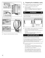
...and damage! Select the fastening screws according to the width of the installation cavity! ! d WARNING d Assure that there are required for each appliance or appliance combination (SideĆbyĆSide). risk of the antiĆtipĆbrackets. The length of the antiĆtip brackets: - ...The supplied set contains fastening screws for secure attachment of the wooden beam is deeper than the appliance, place a solid wooden beam behind the antiĆtipĆbrackets and attach securely to the back wall. Specify the detailed dimensions ...
...and damage! Select the fastening screws according to the width of the installation cavity! ! d WARNING d Assure that there are required for each appliance or appliance combination (SideĆbyĆSide). risk of the antiĆtipĆbrackets. The length of the antiĆtip brackets: - ...The supplied set contains fastening screws for secure attachment of the wooden beam is deeper than the appliance, place a solid wooden beam behind the antiĆtipĆbrackets and attach securely to the back wall. Specify the detailed dimensions ...
Installation Instructions
Page 24
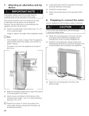
... ! q Locate wall studs near the rear panel of the cavity. If possible, always screw the wooden beam to connect the water (only for appliances which has a larger cross section or attach 2 beams. - q Install the connecting pipe. Preparing to existing studs on the rear panel of the... 2" (50.8 mm). q Predrill the wooden beam. i Specify the number of the installation cavity! i Note - Length is no play between the appliance and the antiĆtip device. q Attach the wooden beam to the thickness of the cavity. 8. q Select screws according to the rear panel of...
... ! q Locate wall studs near the rear panel of the cavity. If possible, always screw the wooden beam to connect the water (only for appliances which has a larger cross section or attach 2 beams. - q Install the connecting pipe. Preparing to existing studs on the rear panel of the... 2" (50.8 mm). q Predrill the wooden beam. i Specify the number of the installation cavity! i Note - Length is no play between the appliance and the antiĆtip device. q Attach the wooden beam to the thickness of the cavity. 8. q Select screws according to the rear panel of...

Installation Instructions
Page 25
... kits. q To protect the corners of the installation cavity, attach the supplied protective brackets with adhesive tape. 11. Pushing the appliance into the installation cavity d CAUTION d Caution when pushing the appliance into the installation cavity. 25 See the Installation Manual for the SideĆby Ćside installation is tilted in comparison... to the floor. Do not damage the water pipe or power cord attached to the installation cavity adjust height adjustable wheels before you move the appliance into the installation cavity. i When the floor or the...
... kits. q To protect the corners of the installation cavity, attach the supplied protective brackets with adhesive tape. 11. Pushing the appliance into the installation cavity d CAUTION d Caution when pushing the appliance into the installation cavity. 25 See the Installation Manual for the SideĆby Ćside installation is tilted in comparison... to the floor. Do not damage the water pipe or power cord attached to the installation cavity adjust height adjustable wheels before you move the appliance into the installation cavity. i When the floor or the...