
U8668 user's manual
Page 4
... IDE devices such as Windows NT, Windows 2000, Windows ME, Windows XP, Novell, LINUX and SCO UNIX. 1-1 Chapter 1 Motherboard Description Notice Introduction of system This mainboard is designed to take advantage of its predecessors, this mainboard continues a commitment to provide you.... 4.Supports popular operating systems such as hard disks and CD-ROM Drives. 3.Supports the Intel Pentium ® 4 processor, a leading edge processor. U8668 Features: 1.Contains on board I/O facilities that include two serial ports, a parallel port, a PS/2 mouse port, a PS/2 keyboard port, audio ports...
... IDE devices such as Windows NT, Windows 2000, Windows ME, Windows XP, Novell, LINUX and SCO UNIX. 1-1 Chapter 1 Motherboard Description Notice Introduction of system This mainboard is designed to take advantage of its predecessors, this mainboard continues a commitment to provide you.... 4.Supports popular operating systems such as hard disks and CD-ROM Drives. 3.Supports the Intel Pentium ® 4 processor, a leading edge processor. U8668 Features: 1.Contains on board I/O facilities that include two serial ports, a parallel port, a PS/2 mouse port, a PS/2 keyboard port, audio ports...
U8668 user's manual
Page 5
... PCI 2.2 compliant. 4.The 66MHz AGP 2.0 compliant interface supports 1x, 2x and 4x data transfer mode. VIA VT8751 (P4M266)/ VT8233A. 2.Chipset - Features Introduction 1-1. Winbond W83697HF. Chapter 1 Motherboard Description Mainboard Features 1. Chipset: 1.Chipset - DRAM Memory: 1.Supports 100MHz or 133MHz SDRAM devices 2.Supports 200MHz, 266MHz DDR SDRAM devices. 3.Supports 64Mb, 128Mb, 256Mb and 512Mb...
... PCI 2.2 compliant. 4.The 66MHz AGP 2.0 compliant interface supports 1x, 2x and 4x data transfer mode. VIA VT8751 (P4M266)/ VT8233A. 2.Chipset - Features Introduction 1-1. Winbond W83697HF. Chapter 1 Motherboard Description Mainboard Features 1. Chipset: 1.Chipset - DRAM Memory: 1.Supports 100MHz or 133MHz SDRAM devices 2.Supports 200MHz, 266MHz DDR SDRAM devices. 3.Supports 64Mb, 128Mb, 256Mb and 512Mb...
U8668 user's manual
Page 6
Chapter 1 Motherboard Description Shadow RAM: Motherboard is equipped with Monitor Power Management protocols. 3.I2C Serial Bus for ROM BIOS. Integrated Savage4 2D/ 3D Graphics Controller and Video Accelerator 1. Contains 3 32-bit ...
Chapter 1 Motherboard Description Shadow RAM: Motherboard is equipped with Monitor Power Management protocols. 3.I2C Serial Bus for ROM BIOS. Integrated Savage4 2D/ 3D Graphics Controller and Video Accelerator 1. Contains 3 32-bit ...
U8668 user's manual
Page 7
... or 24-bit Z-buffering. 11. Microsoft Direct X texture compression. 9. High quality DVD video playback. 11. 2D / 3D resolutions up to 1920x1440. 4. 3D Rendering Features 1. Chapter 1 Motherboard Description 32.. Single-pass multiple textures. 2. Anisotropic filtering. 3. 8-bit stencil buffer. 4. 32-bit true color rendering. 5. Single circle 128-bit 3D architecture. 5. 8M triangles /second...
... or 24-bit Z-buffering. 11. Microsoft Direct X texture compression. 9. High quality DVD video playback. 11. 2D / 3D resolutions up to 1920x1440. 4. 3D Rendering Features 1. Chapter 1 Motherboard Description 32.. Single-pass multiple textures. 2. Anisotropic filtering. 3. 8-bit stencil buffer. 4. 32-bit true color rendering. 5. Single circle 128-bit 3D architecture. 5. 8M triangles /second...

U8668 user's manual
Page 8
Enhanced Parallel Port (EPP). Hardware Monitor Function: 1.Monitors CPU Fan Speed. 2.Monitors System Voltage. Dimensions (MATX form-factor): 24.5cm x 24.5cm (WxL) 1-5 Chapter 1 Motherboard Description AC'97 Sound Codec Onboard: 1.AC-LINK protocol comfliance. 2.Compliant with AC'97 specification. 3.18-bit full duplex stereo ADC, DACs. 4.SNR>95 Bb ...
Enhanced Parallel Port (EPP). Hardware Monitor Function: 1.Monitors CPU Fan Speed. 2.Monitors System Voltage. Dimensions (MATX form-factor): 24.5cm x 24.5cm (WxL) 1-5 Chapter 1 Motherboard Description AC'97 Sound Codec Onboard: 1.AC-LINK protocol comfliance. 2.Compliant with AC'97 specification. 3.18-bit full duplex stereo ADC, DACs. 4.SNR>95 Bb ...
U8668 user's manual
Page 9
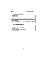
Chapter 1 Motherboard Description 1-2. BIOS & Software 1.Award legal BIOS. 2.Supports APM1.2. 3.Supports USB Function. 4.Supports ACPI. Operating System: Offers the highest performance for MATX Case (Optional). 6.Fully Setup Driver CD. 1-6 Package Contents 1.HDD Cable. 2.FDD Cable. 3.Flash Memory Writer for BIOS Update. 4.USB Cable (Optional). 5.Rear I/O Panel for MS-DOS, Windows NT, Windows 2000, Windows ME, Windows XP, Novell, LINUX, and SCO UNIX etc. 1-3.
Chapter 1 Motherboard Description 1-2. BIOS & Software 1.Award legal BIOS. 2.Supports APM1.2. 3.Supports USB Function. 4.Supports ACPI. Operating System: Offers the highest performance for MATX Case (Optional). 6.Fully Setup Driver CD. 1-6 Package Contents 1.HDD Cable. 2.FDD Cable. 3.Flash Memory Writer for BIOS Update. 4.USB Cable (Optional). 5.Rear I/O Panel for MS-DOS, Windows NT, Windows 2000, Windows ME, Windows XP, Novell, LINUX, and SCO UNIX etc. 1-3.
U8668 user's manual
Page 10
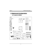
U19 VT8233A Winbond W83697HF SECONDARY IDE CONN. 24 23 FLOPPY DISK CONN. 1 JCMOS1 BIOS 21 JPANEL1 1-7 Layout of U8668 JKBMS1 K/B & Mouse 1 JLAN USB & LAN JCOM1 JKBV1 CPU1 Socket 478 CPU BAT1 COM1 Parallel Port VGA1 JPRNT1 JVGA1 J AT X P W R 2 SPKR-OUT LINE-IN U13 VT8751 J ... SLOT PCI1 JCDIN2 1 J TA D 1 11 PCI SLOT 1 JCODECSEL JCDIN1 PCI SLOT PCI2 PCI3 CNR1 JWOL1 JUSB3 CNR SLOT 1 2 1 10 9 PRIMARY IDE CONN. Mainboard Configuration 2-1. Chapter 1 Motherboard Description 2.
U19 VT8233A Winbond W83697HF SECONDARY IDE CONN. 24 23 FLOPPY DISK CONN. 1 JCMOS1 BIOS 21 JPANEL1 1-7 Layout of U8668 JKBMS1 K/B & Mouse 1 JLAN USB & LAN JCOM1 JKBV1 CPU1 Socket 478 CPU BAT1 COM1 Parallel Port VGA1 JPRNT1 JVGA1 J AT X P W R 2 SPKR-OUT LINE-IN U13 VT8751 J ... SLOT PCI1 JCDIN2 1 J TA D 1 11 PCI SLOT 1 JCODECSEL JCDIN1 PCI SLOT PCI2 PCI3 CNR1 JWOL1 JUSB3 CNR SLOT 1 2 1 10 9 PRIMARY IDE CONN. Mainboard Configuration 2-1. Chapter 1 Motherboard Description 2.
U8668 user's manual
Page 11
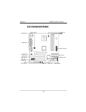
Component Index 1-8 Chapter 1 Motherboard Description 2-2.
Component Index 1-8 Chapter 1 Motherboard Description 2-2.
U8668 user's manual
Page 12
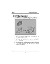
CPU Configuration 3-1. Then Put the fan on the CPU and buckle it and put the fan's power port into the JCFAN1, then to a 90-degree angle. 2. Press the lever down. Pull the lever sideways away from the socket then raise the lever up to complete the installation. 1-9 Locate Pin A in the socket and look for the white dot or cut edge then insert the CPU. 3. Match Pin A with the white dot/cut edge in the CPU. CPU Socket 478 Configuration Steps: CPU Fan CPU 1. Chapter 1 Motherboard Description 3.
CPU Configuration 3-1. Then Put the fan on the CPU and buckle it and put the fan's power port into the JCFAN1, then to a 90-degree angle. 2. Press the lever down. Pull the lever sideways away from the socket then raise the lever up to complete the installation. 1-9 Locate Pin A in the socket and look for the white dot or cut edge then insert the CPU. 3. Match Pin A with the white dot/cut edge in the CPU. CPU Socket 478 Configuration Steps: CPU Fan CPU 1. Chapter 1 Motherboard Description 3.
U8668 user's manual
Page 13
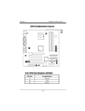
CPU Fan Header: JCFAN1 Pin No. 1 2 3 Assignment Ground +12V Sense 1-10 Chapter 1 Motherboard Description CPU Configuration Layout 3-2.
CPU Fan Header: JCFAN1 Pin No. 1 2 3 Assignment Ground +12V Sense 1-10 Chapter 1 Motherboard Description CPU Configuration Layout 3-2.
U8668 user's manual
Page 14
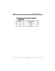
System Fan Header: JSFAN1 (Optional) Pin No. 1 2 3 Assignment Ground +12V Sense 1-11 Chapter 1 Motherboard Description 3-3.
System Fan Header: JSFAN1 (Optional) Pin No. 1 2 3 Assignment Ground +12V Sense 1-11 Chapter 1 Motherboard Description 3-3.
U8668 user's manual
Page 15
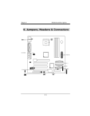
Chapter 1 Motherboard Description 4. Jumpers, Headers & Connectors 1 JKBV1 JATXPWR2 JCODECSEL 1 JWOL1 1 JUSB3 2 10 1 9 JCMOS1 1 JATXPWR1 IDE 1-2 FDD1 JPANEL1 24 23 21 1-12
Chapter 1 Motherboard Description 4. Jumpers, Headers & Connectors 1 JKBV1 JATXPWR2 JCODECSEL 1 JWOL1 1 JUSB3 2 10 1 9 JCMOS1 1 JATXPWR1 IDE 1-2 FDD1 JPANEL1 24 23 21 1-12
U8668 user's manual
Page 16
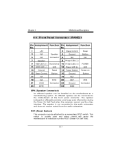
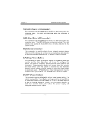
This switch is not connected to the motherboard at the front panel connector. Front Panel Connector: JPANEL1 Pin Assignment Function Pin Assignment Function No. RST (Reset Button) This connector can be attached to ... Ground Connector 23 IRTX 24 IRRX SPK (Speaker Connector) An offboard speaker can be installed on the motherboard as a manufacturing option. Chapter 1 Motherboard Description 4-1. The speaker is usually open and when closed will cause the motherboard to a momentary SPST switch. An offboard speaker can be connected to the audio subsystem and does not...
This switch is not connected to the motherboard at the front panel connector. Front Panel Connector: JPANEL1 Pin Assignment Function Pin Assignment Function No. RST (Reset Button) This connector can be attached to ... Ground Connector 23 IRTX 24 IRRX SPK (Speaker Connector) An offboard speaker can be installed on the motherboard as a manufacturing option. Chapter 1 Motherboard Description 4-1. The speaker is usually open and when closed will cause the motherboard to a momentary SPST switch. An offboard speaker can be connected to the audio subsystem and does not...
U8668 user's manual
Page 17
... be attached to an LED on or off signal. 1-14 ON/OFF (Power Button) This connector can be attached to an infrared sensing device. Chapter 1 Motherboard Description POW-LED (Power LED Connector) This connector can be loaded. To configure this connector. SLP (Sleep/Green Button) This connector is possible. Depressing the...
... be attached to an LED on or off signal. 1-14 ON/OFF (Power Button) This connector can be attached to an infrared sensing device. Chapter 1 Motherboard Description POW-LED (Power LED Connector) This connector can be loaded. To configure this connector. SLP (Sleep/Green Button) This connector is possible. Depressing the...
U8668 user's manual
Page 18
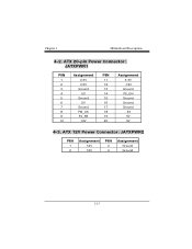
ATX 20-pin Power Connector: JATXPWR1 PIN 1 2 3 4 5 6 7 8 9 10 Assignment 3.3V 3.3V Ground 5V Ground 5V Ground PW_OK 5V_SB 12V PIN 11 12 13 14 15 16 17 18 19 20 Assignment 3.3V -12V Ground PS_ON Ground Ground Ground -5V 5V 5V 4-3. Chapter 1 Motherboard Description 4-2. ATX 12V Power Connector: JATXPWR2 PIN 1 2 Assignment 12V 12V PIN 3 4 Assignment Ground Ground 1-15
ATX 20-pin Power Connector: JATXPWR1 PIN 1 2 3 4 5 6 7 8 9 10 Assignment 3.3V 3.3V Ground 5V Ground 5V Ground PW_OK 5V_SB 12V PIN 11 12 13 14 15 16 17 18 19 20 Assignment 3.3V -12V Ground PS_ON Ground Ground Ground -5V 5V 5V 4-3. Chapter 1 Motherboard Description 4-2. ATX 12V Power Connector: JATXPWR2 PIN 1 2 Assignment 12V 12V PIN 3 4 Assignment Ground Ground 1-15

U8668 user's manual
Page 19
...32-bit Enhanced PCI IDE Controller that supports 360K, 720K, 1.2M, 1.44M and 2.88M floppy disk types. Floppy Disk Connector: FDD1 The motherboard provides a standard floppy disk connector (FDC) that provides PIO Mode 0~4, Bus Master, and Ultra DMA / 33, Ultra DMA / 66,Ultra DMA... / 100 functionality. Chapter 1 Motherboard Description 4-4. This connector supports the provided floppy drive ribbon cables. 4-6. It has two HDD connectors IDE1 (primary) and IDE2 (secondary). • IDE1...
...32-bit Enhanced PCI IDE Controller that supports 360K, 720K, 1.2M, 1.44M and 2.88M floppy disk types. Floppy Disk Connector: FDD1 The motherboard provides a standard floppy disk connector (FDC) that provides PIO Mode 0~4, Bus Master, and Ultra DMA / 33, Ultra DMA / 66,Ultra DMA... / 100 functionality. Chapter 1 Motherboard Description 4-4. This connector supports the provided floppy drive ribbon cables. 4-6. It has two HDD connectors IDE1 (primary) and IDE2 (secondary). • IDE1...

U8668 user's manual
Page 20
... On-board Primary Codec CNR Primary Codec 1-17 Remove AC power line. 2. It is important to follow these instructions closely. ※ Clear CMOS Procedures: 1. Chapter 1 Motherboard Description 4-7. Clear CMOS Jumper: JCMOS1 JCMOS1 1 3 1-2 Closed 1 3 2-3 Closed Assignment Normal Operation (default) Clear CMOS Data The following procedures are for five seconds...
... On-board Primary Codec CNR Primary Codec 1-17 Remove AC power line. 2. It is important to follow these instructions closely. ※ Clear CMOS Procedures: 1. Chapter 1 Motherboard Description 4-7. Clear CMOS Jumper: JCMOS1 JCMOS1 1 3 1-2 Closed 1 3 2-3 Closed Assignment Normal Operation (default) Clear CMOS Data The following procedures are for five seconds...
U8668 user's manual
Page 21
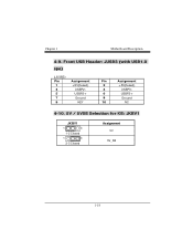
Chapter 1 Motherboard Description 4-9. Front USB Header: JUSB3 (with USB1.0 spe) (JUSB3) Pin 1 3 5 7 9 Assignment +5V(fused) USBP2USBP2+ Ground KEY Pin Assignment 2 +5V(fused) 4 USBP3- 6 USBP3+ 8 Ground 10 NC 4-10. 5V / 5VSB Selection for KB: JKBV1 JKBV1 1 3 1-2 Closed 1 3 2-3 Closed Assignment 5V 5V_SB 1-18
Chapter 1 Motherboard Description 4-9. Front USB Header: JUSB3 (with USB1.0 spe) (JUSB3) Pin 1 3 5 7 9 Assignment +5V(fused) USBP2USBP2+ Ground KEY Pin Assignment 2 +5V(fused) 4 USBP3- 6 USBP3+ 8 Ground 10 NC 4-10. 5V / 5VSB Selection for KB: JKBV1 JKBV1 1 3 1-2 Closed 1 3 2-3 Closed Assignment 5V 5V_SB 1-18
U8668 user's manual
Page 22
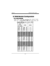
... M 256 M 768 M 512 M 256 M 1256 M 1 G 256 M 640 M 128 M 512 M 768 M 256 M 512 M 1024 M 512 M 512 M 1512 M 1 G 512 M 1128 M 128 M 1 G 1256 M 256 M 1 G 1512 M 512 M 1 G 2 G 1 G 1 G 1-19 Chapter 1 Motherboard Description 5.
... M 256 M 768 M 512 M 256 M 1256 M 1 G 256 M 640 M 128 M 512 M 768 M 256 M 512 M 1024 M 512 M 512 M 1512 M 1 G 512 M 1128 M 128 M 1 G 1256 M 256 M 1 G 1512 M 512 M 1 G 2 G 1 G 1 G 1-19 Chapter 1 Motherboard Description 5.
U8668 user's manual
Page 26
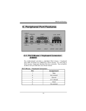
... connect Ground +5 V (fused) Clock No connect 23 You can plug a PS/2 mouse / Keyboard directly into this connector. Mainboard Features 6. PS/2 Mouse / Keyboard Connector: JKBMS1 The motherboard provides a standard PS/2 mouse / Keyboard mini DIN connector for attaching a PS/2 mouse.
... connect Ground +5 V (fused) Clock No connect 23 You can plug a PS/2 mouse / Keyboard directly into this connector. Mainboard Features 6. PS/2 Mouse / Keyboard Connector: JKBMS1 The motherboard provides a standard PS/2 mouse / Keyboard mini DIN connector for attaching a PS/2 mouse.


