
U8668 user's manual
Page 4
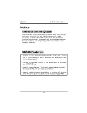
Chapter 1 Motherboard Description Notice Introduction of system This mainboard is designed to take advantage of its predecessors, this mainboard continues a commitment to provide you with PC ATX ... such as hard disks and CD-ROM Drives. 3.Supports the Intel Pentium ® 4 processor, a leading edge processor. Complies with the ultimate solution in data processing. U8668 Features: 1.Contains on board I/O facilities that include two serial ports, a parallel port, a PS/2 mouse port, a PS/2 keyboard port, audio ports, USB ports and a game port...
Chapter 1 Motherboard Description Notice Introduction of system This mainboard is designed to take advantage of its predecessors, this mainboard continues a commitment to provide you with PC ATX ... such as hard disks and CD-ROM Drives. 3.Supports the Intel Pentium ® 4 processor, a leading edge processor. Complies with the ultimate solution in data processing. U8668 Features: 1.Contains on board I/O facilities that include two serial ports, a parallel port, a PS/2 mouse port, a PS/2 keyboard port, audio ports, USB ports and a game port...
U8668 user's manual
Page 5
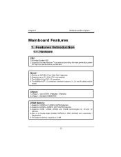
... CPU core speeds. 3.The 33MHz 32 bit PCI 2.2 compliant. 4.The 66MHz AGP 2.0 compliant interface supports 1x, 2x and 4x data transfer mode. Chipset: 1.Chipset - Chapter 1 Motherboard Description Mainboard Features 1. Features Introduction 1-1.
... CPU core speeds. 3.The 33MHz 32 bit PCI 2.2 compliant. 4.The 66MHz AGP 2.0 compliant interface supports 1x, 2x and 4x data transfer mode. Chipset: 1.Chipset - Chapter 1 Motherboard Description Mainboard Features 1. Features Introduction 1-1.
U8668 user's manual
Page 6
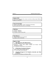
... bus slots Flash Memory: 1.Supports flash memory functionality. 2.Supports ESCD functionality. ROP3 Ternary Raster Operation BitBLTs. 2. 8, 16 and 32 bpp mode acceleration. 3. Chapter 1 Motherboard Description Shadow RAM: Motherboard is equipped with Monitor Power Management protocols. 3.I2C Serial Bus for ROM BIOS. BUS Slots: 1.Contains 1 AGP slot. 2.Contains 1 CNR slot. 3. Green Functionality: 1.Supports...
... bus slots Flash Memory: 1.Supports flash memory functionality. 2.Supports ESCD functionality. ROP3 Ternary Raster Operation BitBLTs. 2. 8, 16 and 32 bpp mode acceleration. 3. Chapter 1 Motherboard Description Shadow RAM: Motherboard is equipped with Monitor Power Management protocols. 3.I2C Serial Bus for ROM BIOS. BUS Slots: 1.Contains 1 AGP slot. 2.Contains 1 CNR slot. 3. Green Functionality: 1.Supports...
U8668 user's manual
Page 7
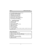
...-pass multiple textures. 2. Single circle 128-bit 3D architecture. 5. 8M triangles /second setup engine. 6. 140M pixels second trilinear fill rate. 7. Massive 2K x 2K textures. 8. Chapter 1 Motherboard Description 32.. Specular lighting and diffuse shading. 6.
...-pass multiple textures. 2. Single circle 128-bit 3D architecture. 5. 8M triangles /second setup engine. 6. 140M pixels second trilinear fill rate. 7. Massive 2K x 2K textures. 8. Chapter 1 Motherboard Description 32.. Specular lighting and diffuse shading. 6.

U8668 user's manual
Page 8
Chapter 1 Motherboard Description AC'97 Sound Codec Onboard: 1.AC-LINK protocol comfliance. 2.Compliant with AC'97 specification. 3.18-bit full duplex stereo ADC, DACs. 4.SNR>95 Bb ...
Chapter 1 Motherboard Description AC'97 Sound Codec Onboard: 1.AC-LINK protocol comfliance. 2.Compliant with AC'97 specification. 3.18-bit full duplex stereo ADC, DACs. 4.SNR>95 Bb ...
U8668 user's manual
Page 9
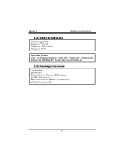
Package Contents 1.HDD Cable. 2.FDD Cable. 3.Flash Memory Writer for BIOS Update. 4.USB Cable (Optional). 5.Rear I/O Panel for MS-DOS, Windows NT, Windows 2000, Windows ME, Windows XP, Novell, LINUX, and SCO UNIX etc. 1-3. Operating System: Offers the highest performance for MATX Case (Optional). 6.Fully Setup Driver CD. 1-6 BIOS & Software 1.Award legal BIOS. 2.Supports APM1.2. 3.Supports USB Function. 4.Supports ACPI. Chapter 1 Motherboard Description 1-2.
Package Contents 1.HDD Cable. 2.FDD Cable. 3.Flash Memory Writer for BIOS Update. 4.USB Cable (Optional). 5.Rear I/O Panel for MS-DOS, Windows NT, Windows 2000, Windows ME, Windows XP, Novell, LINUX, and SCO UNIX etc. 1-3. Operating System: Offers the highest performance for MATX Case (Optional). 6.Fully Setup Driver CD. 1-6 BIOS & Software 1.Award legal BIOS. 2.Supports APM1.2. 3.Supports USB Function. 4.Supports ACPI. Chapter 1 Motherboard Description 1-2.
U8668 user's manual
Page 10
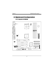
Chapter 1 Motherboard Description 2. Mainboard Configuration 2-1. U19 VT8233A Winbond W83697HF SECONDARY IDE CONN. 24 23 FLOPPY DISK CONN. 1 JCMOS1 BIOS 21 JPANEL1 1-7 Layout of U8668 JKBMS1 K/B & Mouse 1 JLAN USB & LAN JCOM1 JKBV1 CPU1 Socket 478 CPU BAT1 COM1 Parallel Port VGA1 JPRNT1 JVGA1 J AT X P W R 2 SPKR-OUT LINE-IN U13 VT8751 J ...
Chapter 1 Motherboard Description 2. Mainboard Configuration 2-1. U19 VT8233A Winbond W83697HF SECONDARY IDE CONN. 24 23 FLOPPY DISK CONN. 1 JCMOS1 BIOS 21 JPANEL1 1-7 Layout of U8668 JKBMS1 K/B & Mouse 1 JLAN USB & LAN JCOM1 JKBV1 CPU1 Socket 478 CPU BAT1 COM1 Parallel Port VGA1 JPRNT1 JVGA1 J AT X P W R 2 SPKR-OUT LINE-IN U13 VT8751 J ...
U8668 user's manual
Page 11
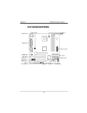
Component Index 1-8 Chapter 1 Motherboard Description 2-2.
Component Index 1-8 Chapter 1 Motherboard Description 2-2.
U8668 user's manual
Page 12
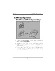
Pull the lever sideways away from the socket then raise the lever up to complete the installation. 1-9 Then Put the fan on the CPU and buckle it and put the fan's power port into the JCFAN1, then to a 90-degree angle. 2. Chapter 1 Motherboard Description 3. Locate Pin A in the CPU. Match Pin A with the white dot/cut edge in the socket and look for the white dot or cut edge then insert the CPU. 3. Press the lever down. CPU Socket 478 Configuration Steps: CPU Fan CPU 1. CPU Configuration 3-1.
Pull the lever sideways away from the socket then raise the lever up to complete the installation. 1-9 Then Put the fan on the CPU and buckle it and put the fan's power port into the JCFAN1, then to a 90-degree angle. 2. Chapter 1 Motherboard Description 3. Locate Pin A in the CPU. Match Pin A with the white dot/cut edge in the socket and look for the white dot or cut edge then insert the CPU. 3. Press the lever down. CPU Socket 478 Configuration Steps: CPU Fan CPU 1. CPU Configuration 3-1.
U8668 user's manual
Page 13
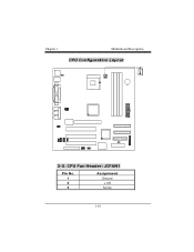
Chapter 1 Motherboard Description CPU Configuration Layout 3-2. CPU Fan Header: JCFAN1 Pin No. 1 2 3 Assignment Ground +12V Sense 1-10
Chapter 1 Motherboard Description CPU Configuration Layout 3-2. CPU Fan Header: JCFAN1 Pin No. 1 2 3 Assignment Ground +12V Sense 1-10
U8668 user's manual
Page 14
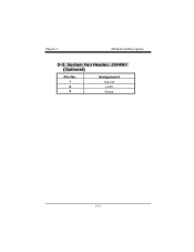
Chapter 1 Motherboard Description 3-3. System Fan Header: JSFAN1 (Optional) Pin No. 1 2 3 Assignment Ground +12V Sense 1-11
Chapter 1 Motherboard Description 3-3. System Fan Header: JSFAN1 (Optional) Pin No. 1 2 3 Assignment Ground +12V Sense 1-11
U8668 user's manual
Page 15
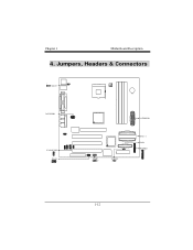
Jumpers, Headers & Connectors 1 JKBV1 JATXPWR2 JCODECSEL 1 JWOL1 1 JUSB3 2 10 1 9 JCMOS1 1 JATXPWR1 IDE 1-2 FDD1 JPANEL1 24 23 21 1-12 Chapter 1 Motherboard Description 4.
Jumpers, Headers & Connectors 1 JKBV1 JATXPWR2 JCODECSEL 1 JWOL1 1 JUSB3 2 10 1 9 JCMOS1 1 JATXPWR1 IDE 1-2 FDD1 JPANEL1 24 23 21 1-12 Chapter 1 Motherboard Description 4.
U8668 user's manual
Page 16
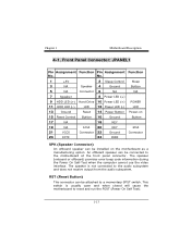
...Hard Drive 10 Power LED (+) POWER 11 HDD LED (-) LED 12 Power LED (-) LED 13 Ground Reset 14 Power Button Power-on the motherboard as a manufacturing option. The speaker (onboard or offboard) provides error beep code information during the Power On Self-Test when the computer cannot .... An offboard speaker can be attached to reset and run the POST (Power On Self Test). 1-13 Chapter 1 Motherboard Description 4-1. This switch is not connected to the motherboard at the front panel connector. Front Panel Connector: JPANEL1 Pin Assignment Function Pin Assignment Function No.
...Hard Drive 10 Power LED (+) POWER 11 HDD LED (-) LED 12 Power LED (-) LED 13 Ground Reset 14 Power Button Power-on the motherboard as a manufacturing option. The speaker (onboard or offboard) provides error beep code information during the Power On Self-Test when the computer cannot .... An offboard speaker can be attached to reset and run the POST (Power On Self Test). 1-13 Chapter 1 Motherboard Description 4-1. This switch is not connected to the motherboard at the front panel connector. Front Panel Connector: JPANEL1 Pin Assignment Function Pin Assignment Function No.
U8668 user's manual
Page 17
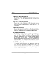
Chapter 1 Motherboard Description POW-LED (Power LED Connector) This connector can be attached to an LED on the front panel of a computer case. HLED (Hard Drive LED ...
Chapter 1 Motherboard Description POW-LED (Power LED Connector) This connector can be attached to an LED on the front panel of a computer case. HLED (Hard Drive LED ...
U8668 user's manual
Page 18
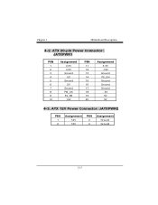
Chapter 1 Motherboard Description 4-2. ATX 12V Power Connector: JATXPWR2 PIN 1 2 Assignment 12V 12V PIN 3 4 Assignment Ground Ground 1-15 ATX 20-pin Power Connector: JATXPWR1 PIN 1 2 3 4 5 6 7 8 9 10 Assignment 3.3V 3.3V Ground 5V Ground 5V Ground PW_OK 5V_SB 12V PIN 11 12 13 14 15 16 17 18 19 20 Assignment 3.3V -12V Ground PS_ON Ground Ground Ground -5V 5V 5V 4-3.
Chapter 1 Motherboard Description 4-2. ATX 12V Power Connector: JATXPWR2 PIN 1 2 Assignment 12V 12V PIN 3 4 Assignment Ground Ground 1-15 ATX 20-pin Power Connector: JATXPWR1 PIN 1 2 3 4 5 6 7 8 9 10 Assignment 3.3V 3.3V Ground 5V Ground 5V Ground PW_OK 5V_SB 12V PIN 11 12 13 14 15 16 17 18 19 20 Assignment 3.3V -12V Ground PS_ON Ground Ground Ground -5V 5V 5V 4-3.

U8668 user's manual
Page 19
... a Master and a Slave drive. Wake On LAN Header: JWOL1 Pin No. 1 2 3 Assignment 5V SB Ground Wake up 1-16 Chapter 1 Motherboard Description 4-4. Hard Disk Connectors: IDE1/IDE2 This mainboard has a 32-bit Enhanced PCI IDE Controller that supports 360K, 720K, 1.2M, 1.44M and ... The IDE2 controller can connect a Master and a Slave drive. This connector supports the provided floppy drive ribbon cables. 4-6. Floppy Disk Connector: FDD1 The motherboard provides a standard floppy disk connector (FDC) that provides PIO Mode 0~4, Bus Master, and Ultra DMA / 33, Ultra DMA / 66,Ultra DMA / ...
... a Master and a Slave drive. Wake On LAN Header: JWOL1 Pin No. 1 2 3 Assignment 5V SB Ground Wake up 1-16 Chapter 1 Motherboard Description 4-4. Hard Disk Connectors: IDE1/IDE2 This mainboard has a 32-bit Enhanced PCI IDE Controller that supports 360K, 720K, 1.2M, 1.44M and ... The IDE2 controller can connect a Master and a Slave drive. This connector supports the provided floppy drive ribbon cables. 4-6. Floppy Disk Connector: FDD1 The motherboard provides a standard floppy disk connector (FDC) that provides PIO Mode 0~4, Bus Master, and Ultra DMA / 33, Ultra DMA / 66,Ultra DMA / ...

U8668 user's manual
Page 20
... Primary Codec 1-17 It is important to follow these instructions closely. ※ Clear CMOS Procedures: 1. Wait for resetting the BIOS password. Make JCMOS1 (1-2) closed . 3. Chapter 1 Motherboard Description 4-7. Remove AC power line. 2.
... Primary Codec 1-17 It is important to follow these instructions closely. ※ Clear CMOS Procedures: 1. Wait for resetting the BIOS password. Make JCMOS1 (1-2) closed . 3. Chapter 1 Motherboard Description 4-7. Remove AC power line. 2.
U8668 user's manual
Page 21
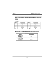
Front USB Header: JUSB3 (with USB1.0 spe) (JUSB3) Pin 1 3 5 7 9 Assignment +5V(fused) USBP2USBP2+ Ground KEY Pin Assignment 2 +5V(fused) 4 USBP3- 6 USBP3+ 8 Ground 10 NC 4-10. 5V / 5VSB Selection for KB: JKBV1 JKBV1 1 3 1-2 Closed 1 3 2-3 Closed Assignment 5V 5V_SB 1-18 Chapter 1 Motherboard Description 4-9.
Front USB Header: JUSB3 (with USB1.0 spe) (JUSB3) Pin 1 3 5 7 9 Assignment +5V(fused) USBP2USBP2+ Ground KEY Pin Assignment 2 +5V(fused) 4 USBP3- 6 USBP3+ 8 Ground 10 NC 4-10. 5V / 5VSB Selection for KB: JKBV1 JKBV1 1 3 1-2 Closed 1 3 2-3 Closed Assignment 5V 5V_SB 1-18 Chapter 1 Motherboard Description 4-9.
U8668 user's manual
Page 22
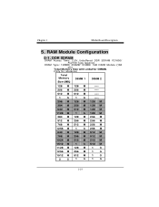
... M 256 M 768 M 512 M 256 M 1256 M 1 G 256 M 640 M 128 M 512 M 768 M 256 M 512 M 1024 M 512 M 512 M 1512 M 1 G 512 M 1128 M 128 M 1 G 1256 M 256 M 1 G 1512 M 512 M 1 G 2 G 1 G 1 G 1-19 Chapter 1 Motherboard Description 5.
... M 256 M 768 M 512 M 256 M 1256 M 1 G 256 M 640 M 128 M 512 M 768 M 256 M 512 M 1024 M 512 M 512 M 1512 M 1 G 512 M 1128 M 128 M 1 G 1256 M 256 M 1 G 1512 M 512 M 1 G 2 G 1 G 1 G 1-19 Chapter 1 Motherboard Description 5.
U8668 user's manual
Page 26
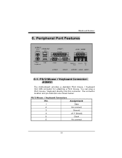
PS/2 Mouse / Keyboard Connector: JKBMS1 The motherboard provides a standard PS/2 mouse / Keyboard mini DIN connector for attaching a PS/2 mouse. The connector location and pin definition are shown below: PS/2 Mouse / Keyboard Connectors ...
PS/2 Mouse / Keyboard Connector: JKBMS1 The motherboard provides a standard PS/2 mouse / Keyboard mini DIN connector for attaching a PS/2 mouse. The connector location and pin definition are shown below: PS/2 Mouse / Keyboard Connectors ...


