
Setup Manual
Page 2
Table of Contents Chapter 1: Introduction 1 1.1 Before You Start 1 1.2 Package Checklist 1 1.3 Motherboard Features 2 1.4 Rear Panel Connectors 3 1.5 Motherboard Layout 4 Chapter 2: Hardware Installation 5 2.1 Installing Central Processing Unit (CPU 5 2.2 FAN Headers 7 2.3 Installing System Memory 8 2.4 Connectors and Slots 10 Chapter 3: Headers & Jumpers Setup 13 3.1 How to Setup ...
Table of Contents Chapter 1: Introduction 1 1.1 Before You Start 1 1.2 Package Checklist 1 1.3 Motherboard Features 2 1.4 Rear Panel Connectors 3 1.5 Motherboard Layout 4 Chapter 2: Hardware Installation 5 2.1 Installing Central Processing Unit (CPU 5 2.2 FAN Headers 7 2.3 Installing System Memory 8 2.4 Connectors and Slots 10 Chapter 3: Headers & Jumpers Setup 13 3.1 How to Setup ...

Setup Manual
Page 6
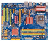
Motherboard Manual 1.5 MOTHERBOARD LAYOUT JKBMS1 JATXPWR1 LGA775 JUSB2 CPU1 JUSB1 JCFAN1 DDR2_A1 DDR2_A2 DDR2_B1 DDR2_B2 BIOS ESATAX1 JUSBV1 JRJ45USB1 JNFAN1 JAUDIO1 J1 Int el P45 JATXPWR2 PEX1_2 LAN PEX16_1 JCMOS1 JSPDIF_OUT2 JCDIN1 PEX1_1 JPE1 JPE3 JPE5 JPE7 JPE2 JPE4 JPE6 JPE8 JPE9 BAT1 Intel ICH10R SATA1 SATA2 PEX16 _2 CODEC PCI1 JSPDIF_OUT1 JAUDIOF1 JCOM1 PCI2 JSPDIF_IN1 FDD1 SATA3 Super IDE I/O IDE1 JUSBV2 JSFAN1 JUSB5 JUSB4 JUSB3 JPANEL1 RSTSW2 PWRSW1 Note: ■ represents the 1st pin. 4
Motherboard Manual 1.5 MOTHERBOARD LAYOUT JKBMS1 JATXPWR1 LGA775 JUSB2 CPU1 JUSB1 JCFAN1 DDR2_A1 DDR2_A2 DDR2_B1 DDR2_B2 BIOS ESATAX1 JUSBV1 JRJ45USB1 JNFAN1 JAUDIO1 J1 Int el P45 JATXPWR2 PEX1_2 LAN PEX16_1 JCMOS1 JSPDIF_OUT2 JCDIN1 PEX1_1 JPE1 JPE3 JPE5 JPE7 JPE2 JPE4 JPE6 JPE8 JPE9 BAT1 Intel ICH10R SATA1 SATA2 PEX16 _2 CODEC PCI1 JSPDIF_OUT1 JAUDIOF1 JCOM1 PCI2 JSPDIF_IN1 FDD1 SATA3 Super IDE I/O IDE1 JUSBV2 JSFAN1 JUSB5 JUSB4 JUSB3 JPANEL1 RSTSW2 PWRSW1 Note: ■ represents the 1st pin. 4

Setup Manual
Page 49
...malfunctioning add-in card. Insert the cards back into the system one of the add-in cards is causing the malfunction. Before declaring the motherboard beyond all expansion cards except the video adapter. If the system video adapter is an integrated part of the system board, the board may... No Flash EPROM detected 10 Flash Erase error 11 Flash Program error 12 "AMIBOOT.ROM" file size error 13 BIOS ROM image mismatch (file layout does not match image present in flash device) POST BIOS Beep Codes Number of Beeps Description 1 Memory refresh timer error 3 Base memory read...
...malfunctioning add-in card. Insert the cards back into the system one of the add-in cards is causing the malfunction. Before declaring the motherboard beyond all expansion cards except the video adapter. If the system video adapter is an integrated part of the system board, the board may... No Flash EPROM detected 10 Flash Erase error 11 Flash Program error 12 "AMIBOOT.ROM" file size error 13 BIOS ROM image mismatch (file layout does not match image present in flash device) POST BIOS Beep Codes Number of Beeps Description 1 Memory refresh timer error 3 Base memory read...

