
User Manual
Page 2
Table of Contents Chapter 1: Introduction 1 1.1 Motherboard Features 1 1.2 Package Checklist 4 1.3 Layout & Components 5 Chapter 2: Hardware Installation 6 2.1 Central Processing Unit (CPU 6 2.2 Fan Headers 8 2.3 Memory Modules Installation 9 2.4 Connectors & Slots 10 Chapter 3: Headers & Jumpers Setup 12 3.1 ...
Table of Contents Chapter 1: Introduction 1 1.1 Motherboard Features 1 1.2 Package Checklist 4 1.3 Layout & Components 5 Chapter 2: Hardware Installation 6 2.1 Central Processing Unit (CPU 6 2.2 Fan Headers 8 2.3 Memory Modules Installation 9 2.4 Connectors & Slots 10 Chapter 3: Headers & Jumpers Setup 12 3.1 ...

User Manual
Page 3
Chipset NVIDIA nForce4 4X: - Note: Do not support Windows 98SE and Windows ME. Supports 10 USB 2.0 ports. - Supports 4 SATA ports, each channel up to 1.5Gb/s. - Supports 4 IDE disk drives ... 4 IDE disk drives. Supports 2 PCI-Express x1 interface slots. - Supports NVIDIA RAID functions, including RAID 0, RAID 1 and RAID 0+1. - Hardware CPU Supports Socket 754. NF44X-A7 CHAPTER 1: INTRODUCTION 1.1 MOTHERBOARD FEATURES A. Supports AMD Athlon 64 and Sempron processors. AMD 64 architecture enables simultaneous 32 and 64 bit computing. Supports HyperTransport Technology and AMD Cool...
Chipset NVIDIA nForce4 4X: - Note: Do not support Windows 98SE and Windows ME. Supports 10 USB 2.0 ports. - Supports 4 SATA ports, each channel up to 1.5Gb/s. - Supports 4 IDE disk drives ... 4 IDE disk drives. Supports 2 PCI-Express x1 interface slots. - Supports NVIDIA RAID functions, including RAID 0, RAID 1 and RAID 0+1. - Hardware CPU Supports Socket 754. NF44X-A7 CHAPTER 1: INTRODUCTION 1.1 MOTHERBOARD FEATURES A. Supports AMD Athlon 64 and Sempron processors. AMD 64 architecture enables simultaneous 32 and 64 bit computing. Supports HyperTransport Technology and AMD Cool...
User Manual
Page 12
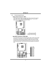
..., so you can connect up to IDE1. The first hard drive should always be connected to four hard disk drives. NF44X-A7 2.4 CONNECTORS & SLOTS Floppy Disk Connector: FDD1 The motherboard provides a standard floppy disk connector that provides PIO Mode 0~5, Bus Master, and Ultra DMA 33/66/100/133 functionality. It... (secondary). IDE1 IDE2 40 39 2 1 10 This connector supports the provided floppy drive ribbon cables. 2 34 1 33 Hard Disk Connectors: IDE1/IDE2 The motherboard has two 32-bit Enhanced PCI IDE Controller that supports 360K, 720K, 1.2M, 1.44M and 2.88M floppy disk types.
..., so you can connect up to IDE1. The first hard drive should always be connected to four hard disk drives. NF44X-A7 2.4 CONNECTORS & SLOTS Floppy Disk Connector: FDD1 The motherboard provides a standard floppy disk connector that provides PIO Mode 0~5, Bus Master, and Ultra DMA 33/66/100/133 functionality. It... (secondary). IDE1 IDE2 40 39 2 1 10 This connector supports the provided floppy drive ribbon cables. 2 34 1 33 Hard Disk Connectors: IDE1/IDE2 The motherboard has two 32-bit Enhanced PCI IDE Controller that supports 360K, 720K, 1.2M, 1.44M and 2.88M floppy disk types.

User Manual
Page 13
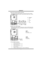
PCI1 PCI2 PCI3 PCI4 PCI-Express Slots: PEX16/ PEX1_1/PEX1_2 PEX16: - Maximum bandwidth is up to 250MB/s per direction. NF44X-A7 Peripheral Component Interconnect Slots: PCI1~PCI4 This motherboard is a bus standard for Peripheral Component Interconnect, and it is equipped with 4 standard PCI slot. PCI stands for expansion cards. Maximum bandwidth is designated as 32 bits. PEX16 PEX1_1 PEX1_2 11 PCI Express 1.0a compliant. - This PCI slot is up to 4GB/s per direction. PEX1_1/PEX1_2: - PCI Express 1.0a compliant. -
PCI1 PCI2 PCI3 PCI4 PCI-Express Slots: PEX16/ PEX1_1/PEX1_2 PEX16: - Maximum bandwidth is up to 250MB/s per direction. NF44X-A7 Peripheral Component Interconnect Slots: PCI1~PCI4 This motherboard is a bus standard for Peripheral Component Interconnect, and it is equipped with 4 standard PCI slot. PCI stands for expansion cards. Maximum bandwidth is designated as 32 bits. PEX16 PEX1_1 PEX1_2 11 PCI Express 1.0a compliant. - This PCI slot is up to 4GB/s per direction. PEX1_1/PEX1_2: - PCI Express 1.0a compliant. -
User Manual
Page 19
...Ground 5 RX6 RX+ 7 Ground JCMOS1: Clear CMOS Header By placing the jumper on the AC. 6. NF44X-A7 Serial ATA Connectors: JSATA1~JSATA4 The motherboard has a SATA Controller in nForce4 4X SLI with 4 channels SATA interface, it allows user to restore the BIOS safe setting and the CMOS data, ...please carefully follow the procedures to avoid damaging the motherboard. 13 Pin 1-2 close: Normal Operation (Default...
...Ground 5 RX6 RX+ 7 Ground JCMOS1: Clear CMOS Header By placing the jumper on the AC. 6. NF44X-A7 Serial ATA Connectors: JSATA1~JSATA4 The motherboard has a SATA Controller in nForce4 4X SLI with 4 channels SATA interface, it allows user to restore the BIOS safe setting and the CMOS data, ...please carefully follow the procedures to avoid damaging the motherboard. 13 Pin 1-2 close: Normal Operation (Default...
User Manual
Page 21
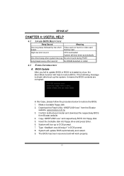
... One Short beep when system boot-up the system, it means the BIOS contents are corrupted. Confirm motherboard model and download the respectively BIOS from the Biostar website: www.biostar.com.tw 3. System will work properly. 19 The BIOS has been recovered and will update BIOS automatically...POST Long beeps every other second No DRAM detected or install 4.2 EXTRA INFORMATION A. System will help to restore the BIOS: 1. NF44X-A7 CHAPTER 4: USEFUL HELP 4.1 AWARD BIOS BEEP CODE Beep Sound Meaning One long beep followed by virus, the Boot-Block function will boo...
... One Short beep when system boot-up the system, it means the BIOS contents are corrupted. Confirm motherboard model and download the respectively BIOS from the Biostar website: www.biostar.com.tw 3. System will work properly. 19 The BIOS has been recovered and will update BIOS automatically...POST Long beeps every other second No DRAM detected or install 4.2 EXTRA INFORMATION A. System will help to restore the BIOS: 1. NF44X-A7 CHAPTER 4: USEFUL HELP 4.1 AWARD BIOS BEEP CODE Beep Sound Meaning One long beep followed by virus, the Boot-Block function will boo...

User Manual
Page 22
... the CMOS data. (See "JCMOS1: Clear CMOS Header" section) 2. The CPU cooler surface is fulfilling with the CPU surface. 2. CPU fan is over heated, the motherboard will shutdown automatically to relief the CPU protection function. 1. Plug in the power cord and boot up the system. Wait for seconds. 2. After confirmed, please... a damage of the CPU, and the system may not power on the system again. 20 Remove the power cord from power supply for seconds. 3. NF44X-A7 B.
... the CMOS data. (See "JCMOS1: Clear CMOS Header" section) 2. The CPU cooler surface is fulfilling with the CPU surface. 2. CPU fan is over heated, the motherboard will shutdown automatically to relief the CPU protection function. 1. Plug in the power cord and boot up the system. Wait for seconds. 2. After confirmed, please... a damage of the CPU, and the system may not power on the system again. 20 Remove the power cord from power supply for seconds. 3. NF44X-A7 B.
User Manual
Page 25
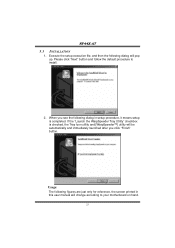
... execution file, and then the following dialog in this user manual will pop up. Please click "Next" button and follow the default procedure to your motherboard on hand. 23 If the "Launch the WarpSpeeder Tray Utility" checkbox is checked, the Tray Icon utility and [WarpSpeeder™] utility will be automatically and...
... execution file, and then the following dialog in this user manual will pop up. Please click "Next" button and follow the default procedure to your motherboard on hand. 23 If the "Launch the WarpSpeeder Tray Utility" checkbox is checked, the Tray Icon utility and [WarpSpeeder™] utility will be automatically and...

