

M7VKQ user's manual
Page 5
BIOS Setup 2-1 2.1 Main Menu 2-3 2.2 Standard CMOS Features 2-6 2.3 Advanced BIOS Features 2-9 2.4 Advanced Chipset Features 2-14 2.5 Integrated Peripherals 2-17 2.6 Power Management Setup 2-22 2.7 PnP/PCI Configurations 2-28 2.8 PC Health Status 2-33 2.9 Frequency Control 2-34 3. Contents 2. Trouble Shooting 3-1 iii
BIOS Setup 2-1 2.1 Main Menu 2-3 2.2 Standard CMOS Features 2-6 2.3 Advanced BIOS Features 2-9 2.4 Advanced Chipset Features 2-14 2.5 Integrated Peripherals 2-17 2.6 Power Management Setup 2-22 2.7 PnP/PCI Configurations 2-28 2.8 PC Health Status 2-33 2.9 Frequency Control 2-34 3. Contents 2. Trouble Shooting 3-1 iii

M7VKQ user's manual
Page 7
... (3.3V). − Support a maximum memory size of any key or any mouse activity. 1-2 Shadow RAM − A memory controller provide shadow RAM and supports 8-bit ROM BIOS. Running at the press of 1GB with SDRAM (512 Mb DRAM technology). LAN Chip Realtek RTL 8100 (Optional). Motherboard Description 1.1 Features 1.1.1 Hardware CPU − −...15 mins. − Wakes from power saving sleep mode at 200/266 MHz Front Side Bus (FSB). Green Function − Support power management operation via BIOS. − Power down timer from 1 to AMD Athlon TM XP 2000+ CPU core speeds.
... (3.3V). − Support a maximum memory size of any key or any mouse activity. 1-2 Shadow RAM − A memory controller provide shadow RAM and supports 8-bit ROM BIOS. Running at the press of 1GB with SDRAM (512 Mb DRAM technology). LAN Chip Realtek RTL 8100 (Optional). Motherboard Description 1.1 Features 1.1.1 Hardware CPU − −...15 mins. − Wakes from power saving sleep mode at 200/266 MHz Front Side Bus (FSB). Green Function − Support power management operation via BIOS. − Power down timer from 1 to AMD Athlon TM XP 2000+ CPU core speeds.
M7VKQ user's manual
Page 11
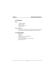
Supports USB Function. Supports APM1.2. Operating System − Offers the highest performance for MS-DOS, Windows NT, Windows 2000, Windows 95/98, Windows ME, Windows XP, SCO UNIX etc. 1.1.3 Accessories − HDD Cable. − FDD Cable. − Flash Memory Writer for BIOS Update. − USB2 Cable (Optional). − Rear I/O Panel for Micro ATX Case (Optional). − Fully Setup Driver CD. 1-6 Supports ACPI. Chapter 1 Motherboard Description 1.1.2 Software BIOS AWARD legal BIOS.
Supports USB Function. Supports APM1.2. Operating System − Offers the highest performance for MS-DOS, Windows NT, Windows 2000, Windows 95/98, Windows ME, Windows XP, SCO UNIX etc. 1.1.3 Accessories − HDD Cable. − FDD Cable. − Flash Memory Writer for BIOS Update. − USB2 Cable (Optional). − Rear I/O Panel for Micro ATX Case (Optional). − Fully Setup Driver CD. 1-6 Supports ACPI. Chapter 1 Motherboard Description 1.1.2 Software BIOS AWARD legal BIOS.
M7VKQ user's manual
Page 12
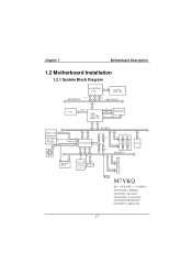
... HOST BUS VGA RGB VIA VT8361 KLE 133 CNTL ADDR MEMORY D ATA I DE I DE AMR SLOT AC' 97 CODEC FLASH BIOS VT82C686B PCI BUS 2 USB CONN. CNTL A DD R / D ATA SER. CONN. M7VKQ Micro ATX(FSB: 133/100MHz) SUPPORTS 2 DIMMS SUPPORT 1 ISA SLOT SUPPORTS 3 PCI SLOTS SUPPORT TELEPHONY SUPPORT 1 AMR SLOT 1-7 PG. 7 CNTL...
... HOST BUS VGA RGB VIA VT8361 KLE 133 CNTL ADDR MEMORY D ATA I DE I DE AMR SLOT AC' 97 CODEC FLASH BIOS VT82C686B PCI BUS 2 USB CONN. CNTL A DD R / D ATA SER. CONN. M7VKQ Micro ATX(FSB: 133/100MHz) SUPPORTS 2 DIMMS SUPPORT 1 ISA SLOT SUPPORTS 3 PCI SLOTS SUPPORT TELEPHONY SUPPORT 1 AMR SLOT 1-7 PG. 7 CNTL...

M7VKQ user's manual
Page 13
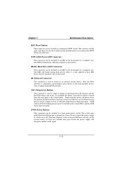
FLOPPY DISK CONN. JPRNT1 JVGA1 SPKR-OUT JATXPWR1 VT8361 GAME Port LINE-IN JCDIN1 MIC-IN AUD_GAME1 1 AMR SLOT JAMRS1 1 JTAD1 1 AMR1 JAUDIO1 2 10 JWOL1 PCI BUS SLOT 19 1 PCI BUS SLOT U1 JNFAN1 1 PCI1 PCI2 PCI3 PCI BUS SLOT ISA1 ISA SLOT IDE1 IDE2 FDD1 1 JSFAN1 VT82C686 BIOS U2 JPANEL1 2 10 1 9 JUSB2 1-8 Chapter 1 Motherboard Description 1.2.2 Layout of Motherboard Model No. SECONDARY IDE CONN. M7VKQ JKBMS1 K/B & Mouse JLAN USB & LAN JCOM1 JKBV1 1 SOCKET A 1 JCFAN1 BAT1 JCMOS1 1 COM1 Parallel Port CPU1 JCLK1 1 DIMM1 DIMM2 VGA1 PRIMARY IDE CONN.
FLOPPY DISK CONN. JPRNT1 JVGA1 SPKR-OUT JATXPWR1 VT8361 GAME Port LINE-IN JCDIN1 MIC-IN AUD_GAME1 1 AMR SLOT JAMRS1 1 JTAD1 1 AMR1 JAUDIO1 2 10 JWOL1 PCI BUS SLOT 19 1 PCI BUS SLOT U1 JNFAN1 1 PCI1 PCI2 PCI3 PCI BUS SLOT ISA1 ISA SLOT IDE1 IDE2 FDD1 1 JSFAN1 VT82C686 BIOS U2 JPANEL1 2 10 1 9 JUSB2 1-8 Chapter 1 Motherboard Description 1.2.2 Layout of Motherboard Model No. SECONDARY IDE CONN. M7VKQ JKBMS1 K/B & Mouse JLAN USB & LAN JCOM1 JKBV1 1 SOCKET A 1 JCFAN1 BAT1 JCMOS1 1 COM1 Parallel Port CPU1 JCLK1 1 DIMM1 DIMM2 VGA1 PRIMARY IDE CONN.

M7VKQ user's manual
Page 16
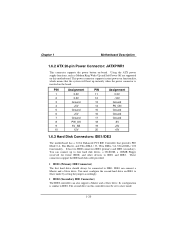
Chapter 1 SOCKET A Motherboard Description J C FA N 1 1 VT8361 DIMM1 DIMM2 JCLK1 1 VT82C686 BIOS JS FA N 1 1 JNFAN1 1 1.3.2 CPU Frequency Selection: JCLK1 JCKL1 *100MHz 1-2 133MHz 2-3 NOTES: The " * " mark indicate primitive value. 1-11
Chapter 1 SOCKET A Motherboard Description J C FA N 1 1 VT8361 DIMM1 DIMM2 JCLK1 1 VT82C686 BIOS JS FA N 1 1 JNFAN1 1 1.3.2 CPU Frequency Selection: JCLK1 JCKL1 *100MHz 1-2 133MHz 2-3 NOTES: The " * " mark indicate primitive value. 1-11

M7VKQ user's manual
Page 20
Expansion slots are not part of adding or enhancing the motherboard's features and capabilities. With these efficient facilities, you can increase the motherboard's capabilities by adding hardware that performs tasks that are a mean of the basic system. SOCKET A DIMM1 DIMM2 AMR Slot PCI Slots ISA Slot VT8361 VT82C686 BIOS 1-15 Chapter 1 Motherboard Description 1.5 Slots The slots in this motherboard are designed to hold expansion cards and connect them to the system bus.
Expansion slots are not part of adding or enhancing the motherboard's features and capabilities. With these efficient facilities, you can increase the motherboard's capabilities by adding hardware that performs tasks that are a mean of the basic system. SOCKET A DIMM1 DIMM2 AMR Slot PCI Slots ISA Slot VT8361 VT82C686 BIOS 1-15 Chapter 1 Motherboard Description 1.5 Slots The slots in this motherboard are designed to hold expansion cards and connect them to the system bus.

M7VKQ user's manual
Page 22
Chapter 1 Motherboard Description 1.6 Connectors, Headers & Jumpers The connectors, headers and jumpers introduced below provide you lots of capabilities such as power supply, front panel signal revelation, IDE hard disk connection, floppy disk connection, Wake On LAN function and USB connection. JKBV1 1 JATXPWR1 JWOL1 1 JAMRS1 1 SOCKET A VT8361 DIMM1 DIMM2 JCMOS1 1 IDE 1-2 FDD1 VT82C686 BIOS JPANEL1 JUSB2 2 10 1 9 1-17 Noticeably, a jumper has two or more pins covered by a plastic jumper cap, allowing the user to select a different system options.
Chapter 1 Motherboard Description 1.6 Connectors, Headers & Jumpers The connectors, headers and jumpers introduced below provide you lots of capabilities such as power supply, front panel signal revelation, IDE hard disk connection, floppy disk connection, Wake On LAN function and USB connection. JKBV1 1 JATXPWR1 JWOL1 1 JAMRS1 1 SOCKET A VT8361 DIMM1 DIMM2 JCMOS1 1 IDE 1-2 FDD1 VT82C686 BIOS JPANEL1 JUSB2 2 10 1 9 1-17 Noticeably, a jumper has two or more pins covered by a plastic jumper cap, allowing the user to select a different system options.
M7VKQ user's manual
Page 24
... hard drives until the system is invoked by any keyboard activity, mouse activity, modem activity or when the sleep button is not in the system BIOS, and the APM driver must be loaded. SLP (Sleep/Green Button) This connector is used to attach to an infrared sensing device. Depressing the button...
... hard drives until the system is invoked by any keyboard activity, mouse activity, modem activity or when the sleep button is not in the system BIOS, and the APM driver must be loaded. SLP (Sleep/Green Button) This connector is used to attach to an infrared sensing device. Depressing the button...
M7VKQ user's manual
Page 25
... has a 32-bit Enhanced PCI IDE Controller that the system will boot up to four hard disk drives, a CD-ROM, a 120MB Floppy (reserved for future BIOS) and other devices to IDE1 and IDE2. Using the ATX power supply functions, such as Modem Ring Wake-Up and Soft Power Off are supported...
... has a 32-bit Enhanced PCI IDE Controller that the system will boot up to four hard disk drives, a CD-ROM, a 120MB Floppy (reserved for future BIOS) and other devices to IDE1 and IDE2. Using the ATX power supply functions, such as Modem Ring Wake-Up and Soft Power Off are supported...
M7VKQ user's manual
Page 38
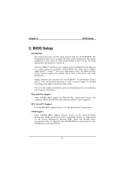
...controls the entire system. ESCD (Extended System Configuration Data) write is turned off. APM Support These AWARD BIOS supports Version 1.1&1.2 of an industry standard BIOS. Sleep and Suspend power management modes are implemented via the System Management Interrupt (SMI). This special information is... then stored in your system by using Setup. Adding important has customized the Award BIOS™, but nonstandard features such as virus and password protection as well as disk drives and serial/ parallel ports. Power ...
...controls the entire system. ESCD (Extended System Configuration Data) write is turned off. APM Support These AWARD BIOS supports Version 1.1&1.2 of an industry standard BIOS. Sleep and Suspend power management modes are implemented via the System Management Interrupt (SMI). This special information is... then stored in your system by using Setup. Adding important has customized the Award BIOS™, but nonstandard features such as virus and password protection as well as disk drives and serial/ parallel ports. Power ...

M7VKQ user's manual
Page 39
...the arrow keys to highlight items, press to select, use the and keys to change entries, press for help and press to navigate in bios Save all the CMOS changes and exit 2-2 The following table provides more detail about how to quit. DRAM Support SDRAM (Synchronous DRAM) are ... Item Help Load previous values from CMOS Load the fail-safe defaults from BIOS default table Load the optimized defaults Menu in the Setup program by using the keyboard. Chapter 2 BIOS Setup PCI Bus Support This AWARD BIOS also supports Version 2.2 of the Intel PCI (Peripheral Component Interconnect) local ...
...the arrow keys to highlight items, press to select, use the and keys to change entries, press for help and press to navigate in bios Save all the CMOS changes and exit 2-2 The following table provides more detail about how to quit. DRAM Support SDRAM (Synchronous DRAM) are ... Item Help Load previous values from CMOS Load the fail-safe defaults from BIOS default table Load the optimized defaults Menu in the Setup program by using the keyboard. Chapter 2 BIOS Setup PCI Bus Support This AWARD BIOS also supports Version 2.2 of the Intel PCI (Peripheral Component Interconnect) local ...

M7VKQ user's manual
Page 40
... functions. Use the arrow keys to select among the items and press to configure enhanced features of the BIOS. 2-3 Figure 1. Chapter 2 BIOS Setup 2.1 Main Menu Once you enter Award BIOS™ CMOS Setup Utility, the Main Menu will appear on board, for reference, please refer to the... BIOS installed on the screen. The information about BIOS defaults on manual (Figure 1,2,3,4,5,6,7,8) is just for update information. The Main Menu allows ...
... functions. Use the arrow keys to select among the items and press to configure enhanced features of the BIOS. 2-3 Figure 1. Chapter 2 BIOS Setup 2.1 Main Menu Once you enter Award BIOS™ CMOS Setup Utility, the Main Menu will appear on board, for reference, please refer to the... BIOS installed on the screen. The information about BIOS defaults on manual (Figure 1,2,3,4,5,6,7,8) is just for update information. The Main Menu allows ...

M7VKQ user's manual
Page 41
PC Health Status This submenu allows you to reload the BIOS when the system is having problems particularly with to enter a password. 2-4 Load Optimized Defaults This selection allows you to monitor the hardware of the system. ... the CMOS Setup Utility. PnP/PCI Configurations This submenu allows you to configure certain IDE hard drive options and Programmed Input/ Output features. Chapter 2 BIOS Setup Advanced Chipset Features This submenu allows you to configure the power management features. Power Management Setup This submenu allows you to configure special chipset...
PC Health Status This submenu allows you to reload the BIOS when the system is having problems particularly with to enter a password. 2-4 Load Optimized Defaults This selection allows you to monitor the hardware of the system. ... the CMOS Setup Utility. PnP/PCI Configurations This submenu allows you to configure certain IDE hard drive options and Programmed Input/ Output features. Chapter 2 BIOS Setup Advanced Chipset Features This submenu allows you to configure the power management features. Power Management Setup This submenu allows you to configure special chipset...

M7VKQ user's manual
Page 42
... submenu allows you to change them. Confirmation message will be displayed before proceeding. Confirmation message will be displayed before proceeding. Chapter 2 BIOS Setup Set User Password If the Supervisor Password is set , then the User Password will function in the same way as the Supervisor Password. If ... is set and the User Password is not set , the "User" will only be able to view configurations but will not be able to update bios. 2-5 Save & Exit Setup Save all changes made during the current session and exit setup.
... submenu allows you to change them. Confirmation message will be displayed before proceeding. Confirmation message will be displayed before proceeding. Chapter 2 BIOS Setup Set User Password If the Supervisor Password is set , then the User Password will function in the same way as the Supervisor Password. If ... is set and the User Password is not set , the "User" will only be able to view configurations but will not be able to update bios. 2-5 Save & Exit Setup Save all changes made during the current session and exit setup.

M7VKQ user's manual
Page 43
Chapter 2 BIOS Setup 2.2 Standard CMOS Features The items in each item. Each category includes no, one or more than one setup items. Use the arrow keys to highlight the item and then use the or keys to select the value you want in Standard CMOS Setup Menu are divided into 10 categories. Standard CMOS Setup 2-6 Figure 2.
Chapter 2 BIOS Setup 2.2 Standard CMOS Features The items in each item. Each category includes no, one or more than one setup items. Use the arrow keys to highlight the item and then use the or keys to select the value you want in Standard CMOS Setup Menu are divided into 10 categories. Standard CMOS Setup 2-6 Figure 2.

M7VKQ user's manual
Page 44
.... IDE Primary Master Options are in Drive B None Video EGA/VGA CGA 40 Select the default video device. Note that you set the date. Chapter 2 BIOS Setup Main Menu Selections This table shows the selections that the 'Day' automatically changes when you can make on the Main Menu. Time HH MM...
.... IDE Primary Master Options are in Drive B None Video EGA/VGA CGA 40 Select the default video device. Note that you set the date. Chapter 2 BIOS Setup Main Menu Selections This table shows the selections that the 'Day' automatically changes when you can make on the Main Menu. Time HH MM...

M7VKQ user's manual
Page 45
Chapter 2 BIOS Setup Item Halt On Base Memory Extended Memory Total Memory Options All Errors No Errors All, but Keyboard All, but Diskette All, but Disk/ Key N/A N/A N/A Description Select the situation in the system. 2-8 Displays the amount of conventional memory detected during boot up . Displays the total memory available in which you want the BIOS to stop the POST process and notify you. Displays the amount of extended memory detected during boot up .
Chapter 2 BIOS Setup Item Halt On Base Memory Extended Memory Total Memory Options All Errors No Errors All, but Keyboard All, but Diskette All, but Disk/ Key N/A N/A N/A Description Select the situation in the system. 2-8 Displays the amount of conventional memory detected during boot up . Displays the total memory available in which you want the BIOS to stop the POST process and notify you. Displays the amount of extended memory detected during boot up .

M7VKQ user's manual
Page 46
Chapter 2 BIOS Setup 2.3 Advanced BIOS Features Figure 3. Virus protection is disabled. If this function is enabled and an attempt is used to the boot sector, BIOS will display a warning message on the screen and sound an alarm beep. Advanced BIOS Setup Virus Warning This option allows you to choose the VIRUS Warning feature that is made to write to protect the IDE Hard Disk boot sector. The Choices: Disabled (default) Enabled Virus protection is activated. 2-9
Chapter 2 BIOS Setup 2.3 Advanced BIOS Features Figure 3. Virus protection is disabled. If this function is enabled and an attempt is used to the boot sector, BIOS will display a warning message on the screen and sound an alarm beep. Advanced BIOS Setup Virus Warning This option allows you to choose the VIRUS Warning feature that is made to write to protect the IDE Hard Disk boot sector. The Choices: Disabled (default) Enabled Virus protection is activated. 2-9

M7VKQ user's manual
Page 47
The Choices: Enabled, Disabled (default). 2-10 Chapter 2 BIOS Setup CPU Internal Cache Depending on the CPU CPU L2 Cache ECC Checking This item allows you to load the operating system from the devices ...in the sequence selected in use, you power up the computer. Disabled Disable cache. First /Second/Third/ Boot Other Device These BIOS attempt to enable/disable CPU L2 Cache ECC Checking. External Cache This option you to enable or disable "Level 2" secondary cache which may be able...
The Choices: Enabled, Disabled (default). 2-10 Chapter 2 BIOS Setup CPU Internal Cache Depending on the CPU CPU L2 Cache ECC Checking This item allows you to load the operating system from the devices ...in the sequence selected in use, you power up the computer. Disabled Disable cache. First /Second/Third/ Boot Other Device These BIOS attempt to enable/disable CPU L2 Cache ECC Checking. External Cache This option you to enable or disable "Level 2" secondary cache which may be able...

