

M7VKQ user's manual
Page 7
Chapter 1 Motherboard Description 1. Shadow RAM − A memory controller provide shadow RAM and supports 8-bit ROM BIOS. Chipset − Chipset - Running at the press of 1GB with SDRAM (512 Mb DRAM technology). Speed &#.... − Wakes from power saving sleep mode at 200/266 MHz Front Side Bus (FSB). DRAM Memory − Supports 32/64/128/256/512MB DIMM module socket. − Supports Synchronous DRAM (3.3V). − Support a maximum memory size of any key or any mouse activity. 1-2 LAN Chip Realtek RTL 8100 (Optional). Green Function...
Chapter 1 Motherboard Description 1. Shadow RAM − A memory controller provide shadow RAM and supports 8-bit ROM BIOS. Chipset − Chipset - Running at the press of 1GB with SDRAM (512 Mb DRAM technology). Speed &#.... − Wakes from power saving sleep mode at 200/266 MHz Front Side Bus (FSB). DRAM Memory − Supports 32/64/128/256/512MB DIMM module socket. − Supports Synchronous DRAM (3.3V). − Support a maximum memory size of any key or any mouse activity. 1-2 LAN Chip Realtek RTL 8100 (Optional). Green Function...
M7VKQ user's manual
Page 8
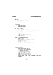
...; Supports LBA mode. Chapter 1 Motherboard Description BUS Slots − Three 32-bit PCI bus master slots. − One ISA slot. − One AMR slot. Flash Memory − Supports flash memory. − Supports ESCD Function.
...; Supports LBA mode. Chapter 1 Motherboard Description BUS Slots − Three 32-bit PCI bus master slots. − One ISA slot. − One AMR slot. Flash Memory − Supports flash memory. − Supports ESCD Function.
M7VKQ user's manual
Page 11
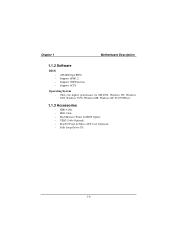
Chapter 1 Motherboard Description 1.1.2 Software BIOS AWARD legal BIOS. Supports APM1.2. Supports USB Function. Supports ACPI. Operating System − Offers the highest performance for MS-DOS, Windows NT, Windows 2000, Windows 95/98, Windows ME, Windows XP, SCO UNIX etc. 1.1.3 Accessories − HDD Cable. − FDD Cable. − Flash Memory Writer for BIOS Update. − USB2 Cable (Optional). − Rear I/O Panel for Micro ATX Case (Optional). − Fully Setup Driver CD. 1-6
Chapter 1 Motherboard Description 1.1.2 Software BIOS AWARD legal BIOS. Supports APM1.2. Supports USB Function. Supports ACPI. Operating System − Offers the highest performance for MS-DOS, Windows NT, Windows 2000, Windows 95/98, Windows ME, Windows XP, SCO UNIX etc. 1.1.3 Accessories − HDD Cable. − FDD Cable. − Flash Memory Writer for BIOS Update. − USB2 Cable (Optional). − Rear I/O Panel for Micro ATX Case (Optional). − Fully Setup Driver CD. 1-6
M7VKQ user's manual
Page 12
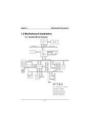
M7VKQ Micro ATX(FSB: 133/100MHz) SUPPORTS 2 DIMMS SUPPORT 1 ISA SLOT SUPPORTS 3 PCI SLOTS SUPPORT TELEPHONY SUPPORT 1 AMR SLOT 1-7 CNTL A DD R / D ATA SER. Chapter 1 Motherboard Description 1.2 ... Installation 1.2.1 System Block Diagram SOCKET 462 CPU CLOCK ICW 230 CONTROL HOST BUS ADD DATA HOST BUS VGA RGB VIA VT8361 KLE 133 CNTL ADDR MEMORY D ATA I DE I DE AMR SLOT AC' 97 CODEC FLASH BIOS VT82C686B PCI BUS 2 USB CONN. PG. 7 CNTL PG. 13 US B US B US B US B A D D R/ D ATA PG...
M7VKQ Micro ATX(FSB: 133/100MHz) SUPPORTS 2 DIMMS SUPPORT 1 ISA SLOT SUPPORTS 3 PCI SLOTS SUPPORT TELEPHONY SUPPORT 1 AMR SLOT 1-7 CNTL A DD R / D ATA SER. Chapter 1 Motherboard Description 1.2 ... Installation 1.2.1 System Block Diagram SOCKET 462 CPU CLOCK ICW 230 CONTROL HOST BUS ADD DATA HOST BUS VGA RGB VIA VT8361 KLE 133 CNTL ADDR MEMORY D ATA I DE I DE AMR SLOT AC' 97 CODEC FLASH BIOS VT82C686B PCI BUS 2 USB CONN. PG. 7 CNTL PG. 13 US B US B US B US B A D D R/ D ATA PG...

M7VKQ user's manual
Page 18
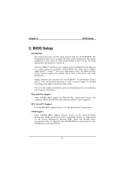
Total Memory Size (MB) 64 M 128 M 256 M 512 M 128 M 256 M 512 M 1024 M 160 M 288 M 544 M 192 M 320 M 576 M 192 M 384 M 640 M 320 M 384 M 768 M 576 M 640 M 768 M ...
Total Memory Size (MB) 64 M 128 M 256 M 512 M 128 M 256 M 512 M 1024 M 160 M 288 M 544 M 192 M 320 M 576 M 192 M 384 M 640 M 320 M 384 M 768 M 576 M 640 M 768 M ...

M7VKQ user's manual
Page 19
The Mounting Holes and plastic tabs should fit over the edge and hold the DIMM memory modules in one direction. 2. Chapter 1 Motherboard Description 1.4.2 How to install a DIMM Module 1. Insert the DIMM memory modules into the socket at a 90-degree angle, and then push down vertically so that it will fit into the slot in place. 1-14 The DIMM socket has a " Plastic Safety Tab", and the DIMM memory module has an "Asymmetrical notch", so the DIMM memory module can only fit into the place. 3. Push the tabs out.
The Mounting Holes and plastic tabs should fit over the edge and hold the DIMM memory modules in one direction. 2. Chapter 1 Motherboard Description 1.4.2 How to install a DIMM Module 1. Insert the DIMM memory modules into the socket at a 90-degree angle, and then push down vertically so that it will fit into the slot in place. 1-14 The DIMM socket has a " Plastic Safety Tab", and the DIMM memory module has an "Asymmetrical notch", so the DIMM memory module can only fit into the place. 3. Push the tabs out.
M7VKQ user's manual
Page 38
... Plug and Play specification Version 1.0A complicant. EPA Green PC Support This AWARD BIOS supports Version 1.03 of configuring your computer system's ROM (Read Only Memory) is turned off. Power management features are supported. Sleep and Suspend power management modes are implemented via the System Management Interrupt (SMI). The Award BIOS...
... Plug and Play specification Version 1.0A complicant. EPA Green PC Support This AWARD BIOS supports Version 1.03 of configuring your computer system's ROM (Read Only Memory) is turned off. Power management features are supported. Sleep and Suspend power management modes are implemented via the System Management Interrupt (SMI). The Award BIOS...

M7VKQ user's manual
Page 42
Exit Without Saving Abandon all configuration changes to CMOS (memory) and exit setup. Confirmation message will be displayed before proceeding. Update BIOS This submenu allows you to update bios. 2-5 Confirmation message will be able to ...
Exit Without Saving Abandon all configuration changes to CMOS (memory) and exit setup. Confirmation message will be displayed before proceeding. Update BIOS This submenu allows you to update bios. 2-5 Confirmation message will be able to ...

M7VKQ user's manual
Page 45
Displays the amount of extended memory detected during boot up . Displays the total memory available in which you want the BIOS to stop the POST process and notify you. Displays the amount of conventional memory detected during boot up . Chapter 2 BIOS Setup Item Halt On Base Memory Extended Memory Total Memory Options All Errors No Errors All, but Keyboard All, but Diskette All, but Disk/ Key N/A N/A N/A Description Select the situation in the system. 2-8
Displays the amount of extended memory detected during boot up . Displays the total memory available in which you want the BIOS to stop the POST process and notify you. Displays the amount of conventional memory detected during boot up . Chapter 2 BIOS Setup Item Halt On Base Memory Extended Memory Total Memory Options All Errors No Errors All, but Keyboard All, but Diskette All, but Disk/ Key N/A N/A N/A Description Select the situation in the system. 2-8

M7VKQ user's manual
Page 47
... version of the Power On Self-Test (POST) to execute after you to enable or disable "Level 2" secondary cache which may be able to increase memory access time with two floppy drives, this option allows you to swap logical drive assignments. The Choices: Disabled (default), Enabled. The Choices: Enabled, Disabled (default...
... version of the Power On Self-Test (POST) to execute after you to enable or disable "Level 2" secondary cache which may be able to increase memory access time with two floppy drives, this option allows you to swap logical drive assignments. The Choices: Disabled (default), Enabled. The Choices: Enabled, Disabled (default...
M7VKQ user's manual
Page 49
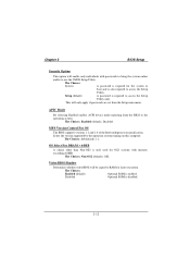
... enables ACPI device mode reporting from the Setup main menu. The Choices: 1.4 (default), 1.1. Chapter 2 BIOS Setup Security Option This option will enable only individuals with memory exceeding 64MB. Setup (default) A password is required for OS2 systems with passwords to bring the system online and/or to RAM for faster execution. The...
... enables ACPI device mode reporting from the Setup main menu. The Choices: 1.4 (default), 1.1. Chapter 2 BIOS Setup Security Option This option will enable only individuals with memory exceeding 64MB. Setup (default) A password is required for OS2 systems with passwords to bring the system online and/or to RAM for faster execution. The...

M7VKQ user's manual
Page 51
... manages bus speeds and access to configure the specific features of the chipset installed on your system have been changed unless you to the system memory resources, such as DRAM and external cache. Figure 4. Chapter 2 BIOS Setup 2.4 Advanced Chipset Features This submenu allows you are suspicious that came with the PCI...
... manages bus speeds and access to configure the specific features of the chipset installed on your system have been changed unless you to the system memory resources, such as DRAM and external cache. Figure 4. Chapter 2 BIOS Setup 2.4 Advanced Chipset Features This submenu allows you are suspicious that came with the PCI...
M7VKQ user's manual
Page 52
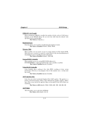
... 64M (default),256M, 128M, 64M, 32M, 16M, 8M, 4M. The Choices: Enabled (default), Disabled. The aperture is a portion of system memory for more information. Host cycles that the cache controller is enabled. Bank Interleave This item allows you to the user documentation of the video BIOS..., resulting in better system performance. Memory Hole When enabled, you are forwarded to the AGP without any program writes to enable or disable the bank interleave feature. The...
... 64M (default),256M, 128M, 64M, 32M, 16M, 8M, 4M. The Choices: Enabled (default), Disabled. The aperture is a portion of system memory for more information. Host cycles that the cache controller is enabled. Bank Interleave This item allows you to the user documentation of the video BIOS..., resulting in better system performance. Memory Hole When enabled, you are forwarded to the AGP without any program writes to enable or disable the bank interleave feature. The...

M7VKQ user's manual
Page 58
MPU-401 Enable or Disable MPU-401 function. The Choices: 300-303H, 310-313H, 320-323H, 330-333H (default). The Choices: Enabled (default), Disabled. 2-21 The Choices: Disabled (default), Enabled. Chapter 2 BIOS Setup SB DMA Select Change the SoundBlaster Pro direct memory access setting. MPU-401 I/O Address Change the SoundBlaster Pro MPU-401 I/O address. The Choices: DMA0, DMA1 (default), DMA2, DMA3. Game Port (200-207H) Change the joystick connects port address.
MPU-401 Enable or Disable MPU-401 function. The Choices: 300-303H, 310-313H, 320-323H, 330-333H (default). The Choices: Enabled (default), Disabled. 2-21 The Choices: Disabled (default), Enabled. Chapter 2 BIOS Setup SB DMA Select Change the SoundBlaster Pro direct memory access setting. MPU-401 I/O Address Change the SoundBlaster Pro MPU-401 I/O address. The Choices: DMA0, DMA1 (default), DMA2, DMA3. Game Port (200-207H) Change the joystick connects port address.

M7VKQ user's manual
Page 66
... in the system BIOS. This node records which resources are no IRQ/DMA and I/O port conflicts. 2-29 Be sure that a resource is assigned to the memory locations.
... in the system BIOS. This node records which resources are no IRQ/DMA and I/O port conflicts. 2-29 Be sure that a resource is assigned to the memory locations.

M7VKQ user's manual
Page 72
..., reset circuit breaker or replace fuse. PROBABLE CAUSE DIAGNOSIS SOLUTION Power cable is partially dislodged from the slot on the motherboard. PROBABLE CAUSE DIAGNOSIS SOLUTION Memory DIMM is unplugged. Turn off system unit. Take Using even pressure on . Make sure power cable is still dead. socket are lit, hard drive is...
..., reset circuit breaker or replace fuse. PROBABLE CAUSE DIAGNOSIS SOLUTION Power cable is partially dislodged from the slot on the motherboard. PROBABLE CAUSE DIAGNOSIS SOLUTION Memory DIMM is unplugged. Turn off system unit. Take Using even pressure on . Make sure power cable is still dead. socket are lit, hard drive is...

M7VKQ user's manual
Page 75
PROBLEM Screen goes blank periodically. Keyboard failure. Check keys again, if no improvement replace keyboard. 3-4 Computer virus. Use anti-virus programs to detect and clean viruses. Reinstall memory, make sure that all memory modules are installed in correct sockets. DIAGNOSIS SOLUTION Disable screen saver. PROBLEM PROBABLE CAUSE Memory problem. Chapter 3 Trouble Shooting No screen. DIAGNOSIS SOLUTION Reboot computer. PROBABLE CAUSE Screen saver is disconnected. PROBLEM PROBABLE CAUSE Keyboard is enabled. DIAGNOSIS SOLUTION Reconnect keyboard.
PROBLEM Screen goes blank periodically. Keyboard failure. Check keys again, if no improvement replace keyboard. 3-4 Computer virus. Use anti-virus programs to detect and clean viruses. Reinstall memory, make sure that all memory modules are installed in correct sockets. DIAGNOSIS SOLUTION Disable screen saver. PROBLEM PROBABLE CAUSE Memory problem. Chapter 3 Trouble Shooting No screen. DIAGNOSIS SOLUTION Reboot computer. PROBABLE CAUSE Screen saver is disconnected. PROBLEM PROBABLE CAUSE Keyboard is enabled. DIAGNOSIS SOLUTION Reconnect keyboard.

M7VKQ compatibility test report
Page 2
CONTENTS PRODUCT INFORMATION 5 Motherboard General Information 5 Chipset Details ...5 BIOS Details ...5 CPU Supports...5 Memory Supports...5 On-board Features and Devices 5 Mechanical ...6 DESIGN REVIEW 8 Mainboard Voltage Measurement 8 Bus Clock ...8 REQUIRED BIOS DEFAULT SETTINGS 9 BIOS FEATURES SETUP 9 CHIPSET FEATURES SETUP 9 POWER ...
CONTENTS PRODUCT INFORMATION 5 Motherboard General Information 5 Chipset Details ...5 BIOS Details ...5 CPU Supports...5 Memory Supports...5 On-board Features and Devices 5 Mechanical ...6 DESIGN REVIEW 8 Mainboard Voltage Measurement 8 Bus Clock ...8 REQUIRED BIOS DEFAULT SETTINGS 9 BIOS FEATURES SETUP 9 CHIPSET FEATURES SETUP 9 POWER ...

M7VKQ compatibility test report
Page 3
Joystick...43 Keyboard ...44 LAN Card...44 LAN HUB ...45 Memory ...45 Modem Card...46 Mouse ...46 Monitor...47 Power Supply ...47 Printer ...48 Scanner ...48 SCSI Card...48 Sound Card...49 USB HUB...49 ZIP/...
Joystick...43 Keyboard ...44 LAN Card...44 LAN HUB ...45 Memory ...45 Modem Card...46 Mouse ...46 Monitor...47 Power Supply ...47 Printer ...48 Scanner ...48 SCSI Card...48 Sound Card...49 USB HUB...49 ZIP/...

M7VKQ compatibility test report
Page 5
...Support CNR Slot Support 1 2 3 4 None Yes No Yes No ACR Slot Support Yes No Number of Memory Supported ECC Support SDRAM 1024 (MB) DIMM 2 . PRODUCT INFORMATION Motherboard General Information Vendor Biostar Model Number Version Number Platform M7 VKQ V0.90/V0.92/V1.0/V1.1 AT ATX Micro ATX Flex ATX... XP AMD Duron Max =1400 MHz Max =2000+ Max =1300 MHz Max =133 MHz Max =133 MHz Max =100 MHz Memory Supports Maximum Memory Support Number of Memory Slots Type of Shared Slots 1 None 100/133 MHz Front Side Bus Supports Yes No PCI v2.2 Compliance Yes No ATA-3 Compliance...
...Support CNR Slot Support 1 2 3 4 None Yes No Yes No ACR Slot Support Yes No Number of Memory Supported ECC Support SDRAM 1024 (MB) DIMM 2 . PRODUCT INFORMATION Motherboard General Information Vendor Biostar Model Number Version Number Platform M7 VKQ V0.90/V0.92/V1.0/V1.1 AT ATX Micro ATX Flex ATX... XP AMD Duron Max =1400 MHz Max =2000+ Max =1300 MHz Max =133 MHz Max =133 MHz Max =100 MHz Memory Supports Maximum Memory Support Number of Memory Slots Type of Shared Slots 1 None 100/133 MHz Front Side Bus Supports Yes No PCI v2.2 Compliance Yes No ATA-3 Compliance...


