
MANUAL
Page 6
... AC'97 Audio Sound Codec 4 Chip: ALC850. 4 Compliant with PCI-Express Version 1.a specification. Supports NVIDIA Firewall. - Please check the website: http://www.biostar.com.tw/products/mainboard/board.php3?name=K8NBD-S9 4 Maximum memory size is 2 GB Caution: ...Maximum theoretical realized bandwidth of 4GB/s simultaneously per direction, for an aggregate of 8GB/s totally. Hardware CPU 4 Supports AMD Socket 939. 4 Supports AMD Athlon 64 FX processor. 4 Supports AMD Athlon 64 processor. 4 Supports AMD Sempron processor. 4 AMD 64 architecture enables simultaneous 32 and 64 bit computing...
... AC'97 Audio Sound Codec 4 Chip: ALC850. 4 Compliant with PCI-Express Version 1.a specification. Supports NVIDIA Firewall. - Please check the website: http://www.biostar.com.tw/products/mainboard/board.php3?name=K8NBD-S9 4 Maximum memory size is 2 GB Caution: ...Maximum theoretical realized bandwidth of 4GB/s simultaneously per direction, for an aggregate of 8GB/s totally. Hardware CPU 4 Supports AMD Socket 939. 4 Supports AMD Athlon 64 FX processor. 4 Supports AMD Athlon 64 processor. 4 Supports AMD Sempron processor. 4 AMD 64 architecture enables simultaneous 32 and 64 bit computing...
MANUAL
Page 9
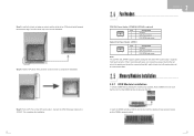
... Control 3 FAN RPM rate sense System Fan Power Header: JSFAN1 31 Pin Assignment 1 Ground 2 CPU Fan Control 3 FAN RPM rate sense Note: The JCFAN1 and JSFAN1 support system cooling fan with wires onto connectors, please note that the notch on the DIMM matches the ...GND. 2.5 Memory Modules Installation 2.5.1 DDR Module installation 1. Connect the CPU FAN power cable to complete the installation. Step 5: Put the CPU Fan on CPU should be connected to pin#2, and the black wire is properly seated. It supports 3 pin head connector. Unlock a DIMM slot by pressing the retaining...
... Control 3 FAN RPM rate sense System Fan Power Header: JSFAN1 31 Pin Assignment 1 Ground 2 CPU Fan Control 3 FAN RPM rate sense Note: The JCFAN1 and JSFAN1 support system cooling fan with wires onto connectors, please note that the notch on the DIMM matches the ...GND. 2.5 Memory Modules Installation 2.5.1 DDR Module installation 1. Connect the CPU FAN power cable to complete the installation. Step 5: Put the CPU Fan on CPU should be connected to pin#2, and the black wire is properly seated. It supports 3 pin head connector. Unlock a DIMM slot by pressing the retaining...
MANUAL
Page 10
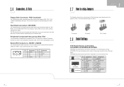
...Pin Assignment Pin Assignment 1 Ground 2 TX+ 3 TX- 4 Ground 5 RX- 6 RX+ 7 Ground 2.7 How to setup Jumpers The illustration shows how to CPU power circuit. The IDE connectors can connect a master and a slave drive, so you can connect up jumpers. Pin opened Pin closed 2.8 Detail Settings Pin1-2 ...and it will provide +12V to connect 12-pin power connector on pins, the jumper is designated as 32 bits. This connector supports the provided floppy drive ribbon cables. The first hard drive should always be connected to four hard disk drives. Serial ATA Connectors: ...
...Pin Assignment Pin Assignment 1 Ground 2 TX+ 3 TX- 4 Ground 5 RX- 6 RX+ 7 Ground 2.7 How to setup Jumpers The illustration shows how to CPU power circuit. The IDE connectors can connect a master and a slave drive, so you can connect up jumpers. Pin opened Pin closed 2.8 Detail Settings Pin1-2 ...and it will provide +12V to connect 12-pin power connector on pins, the jumper is designated as 32 bits. This connector supports the provided floppy drive ribbon cables. The first hard drive should always be connected to four hard disk drives. Serial ATA Connectors: ...


