
User Manual
Page 4
Table of the Contents Section 1 Introduction 1.1 Begin Your Tour In The DIY World 2 1.2 Checking the Equipments 3 Section 2 Motherboard Set Up 2.1 Motherboard Features 6 2.2 Layout & Components 10 2.3 Installing Central Processing Unit (CPU 11 2.4 Fan Headers 13 2.5 Installing System Memory 14 2.6 Connectors, & Slots 15 2.7 How to setup Jumpers 17 2.8 ...
Table of the Contents Section 1 Introduction 1.1 Begin Your Tour In The DIY World 2 1.2 Checking the Equipments 3 Section 2 Motherboard Set Up 2.1 Motherboard Features 6 2.2 Layout & Components 10 2.3 Installing Central Processing Unit (CPU 11 2.4 Fan Headers 13 2.5 Installing System Memory 14 2.6 Connectors, & Slots 15 2.7 How to setup Jumpers 17 2.8 ...
User Manual
Page 7
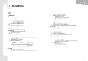
2.1 Motherboard Features Model : P4TBE � A. Hardware CPU 4 Supports LGA 775. 4 Supports single Intel Pentium 4 processor. 4 Front Side Bus at the following frequency ranges: - 533 MT/s (133 ...
2.1 Motherboard Features Model : P4TBE � A. Hardware CPU 4 Supports LGA 775. 4 Supports single Intel Pentium 4 processor. 4 Front Side Bus at the following frequency ranges: - 533 MT/s (133 ...
User Manual
Page 11
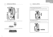
Super I /O BIOS Grantsdale-G BAT1 Intel ICH6R Giga LAN IEEE1394 Chip Codec FDD1 16 15 21 IDE1: Hard Disk Connector The motherboard has a 32-bit Enhanced PCI IDE Controller that provides PIO Mode 0~5, Bus Master, and Ultra DMA 33/ 66/ 100 functionality. Unlock a DIMM slot by ...the slot until the retaining chip snap back in place and the DIMM is properly seated. 2.6 Connectors and Slots FDD1: Floppy Disk Connector (optional) The motherboard provides a standard floppy disk connector that the notch on the DIMM matches the break on the slot such that supports 360K, 720K, 1.2M, 1.44M and...
Super I /O BIOS Grantsdale-G BAT1 Intel ICH6R Giga LAN IEEE1394 Chip Codec FDD1 16 15 21 IDE1: Hard Disk Connector The motherboard has a 32-bit Enhanced PCI IDE Controller that provides PIO Mode 0~5, Bus Master, and Ultra DMA 33/ 66/ 100 functionality. Unlock a DIMM slot by ...the slot until the retaining chip snap back in place and the DIMM is properly seated. 2.6 Connectors and Slots FDD1: Floppy Disk Connector (optional) The motherboard provides a standard floppy disk connector that the notch on the DIMM matches the break on the slot such that supports 360K, 720K, 1.2M, 1.44M and...
User Manual
Page 12
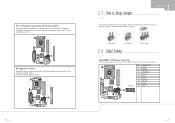
... SB Volt. 5 Ground 6 +5V 7 +3.3V 8 Ground 9 PS_ON 10 +12V 11 Ground 12 +5V Giga LAN IEEE1394 Chip Codec 7 12 PCI 1: Peripheral Component Interconnect Slots This motherboard is designated as 32 bits.
... SB Volt. 5 Ground 6 +5V 7 +3.3V 8 Ground 9 PS_ON 10 +12V 11 Ground 12 +5V Giga LAN IEEE1394 Chip Codec 7 12 PCI 1: Peripheral Component Interconnect Slots This motherboard is designated as 32 bits.
User Manual
Page 14
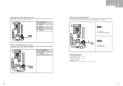
.... 4. Set the jumper to "Pin 1-2 close ". 3. JCMOS1 13 13 Pin 2-3 Close: Clear CMOS data. SATA1/SATA2: Serial ATA Connectors The motherboard has a PCI to SATA Controller with 2 channels SATA interface, it allows user to restore the BIOS safe setting and the CMOS data, please carefully follow... the procedures to avoid damaging the motherboard. 13 Super I /O BIOS Grantsdale-G Pin Assignment 1 Ground 2 TX+2 3 TX4 Ground 5 RX6 RX+4 7 Ground BAT1 Intel ICH6R Giga LAN IEEE1394...
.... 4. Set the jumper to "Pin 1-2 close ". 3. JCMOS1 13 13 Pin 2-3 Close: Clear CMOS data. SATA1/SATA2: Serial ATA Connectors The motherboard has a PCI to SATA Controller with 2 channels SATA interface, it allows user to restore the BIOS safe setting and the CMOS data, please carefully follow... the procedures to avoid damaging the motherboard. 13 Super I /O BIOS Grantsdale-G Pin Assignment 1 Ground 2 TX+2 3 TX4 Ground 5 RX6 RX+4 7 Ground BAT1 Intel ICH6R Giga LAN IEEE1394...

