Update Manual
Page 1
... location for your agreement to request your backup BIOS file in the system. While the system boots up and the full screen logo shows up to start the update procedure. 5. BIOS update utility 1. After the BIOS Update process is completed. Download the proper BIOS from the DVD Driver. 2. After entering the BIOS setup, please go to the Save & Exit, using the Restore Defaults function to load Optimized Defaults, and select Save Changes and Reset to enter BIOS setup...
... location for your agreement to request your backup BIOS file in the system. While the system boots up and the full screen logo shows up to start the update procedure. 5. BIOS update utility 1. After the BIOS Update process is completed. Download the proper BIOS from the DVD Driver. 2. After entering the BIOS setup, please go to the Save & Exit, using the Restore Defaults function to load Optimized Defaults, and select Save Changes and Reset to enter BIOS setup...
Update Manual
Page 2
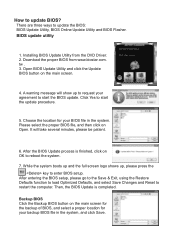
... to enter BIOS setup. Installing BIOS Update Utility from the DVD Driver. 2. While the system boots up and the full screen logo shows up to request your agreement to proceed. 7. Please make sure the system is completed. Online Update Utility 1. Open BIOS Update Utility and click the Online Update button on the main screen. 4. Then, the BIOS Update is connected to the internet before using the Restore Defaults function to load Optimized Defaults, and select Save Changes and Reset...
... to enter BIOS setup. Installing BIOS Update Utility from the DVD Driver. 2. While the system boots up and the full screen logo shows up to request your agreement to proceed. 7. Please make sure the system is completed. Online Update Utility 1. Open BIOS Update Utility and click the Online Update button on the main screen. 4. Then, the BIOS Update is connected to the internet before using the Restore Defaults function to load Optimized Defaults, and select Save Changes and Reset...
Update Manual
Page 3
... USB pen drive. 1. For better performance, the software is built in the BIOS ROM. Choose [fs0] to the USB port. 4. After entering the BIOS setup, please go to the Save & Exit, using the Restore Defaults function to load Optimized Defaults, and select Save Changes and Reset to system boot failure. The information and pictures described above about the software are subject to restart the system. This utility only allows storage device with BIOSTAR BIOS...
... USB pen drive. 1. For better performance, the software is built in the BIOS ROM. Choose [fs0] to the USB port. 4. After entering the BIOS setup, please go to the Save & Exit, using the Restore Defaults function to load Optimized Defaults, and select Save Changes and Reset to system boot failure. The information and pictures described above about the software are subject to restart the system. This utility only allows storage device with BIOSTAR BIOS...
Setup Manual
Page 4
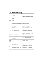
...Supports PCI-E Gen2 x1 expansion cards 2 Motherboard Manual 1.3 MOTHERBOARD FEATURES SPEC Supports Execute Disable Bit / Enhanced Intel Socket 1155 SpeedStep® / Intel Architecture-64 / Extended CPU Intel Core i7 / i5 / i3 / Pentium / Celeron Memory 64 Technology / Virtualization Technology / processor Hyper Threading Chipset Intel H77 IT8728 Environment Control initiatives, Super I/O Provides the most commonly used legacy Super I/O functionality. SATA Version 2.0 / 3.0 specification compliant RAID 0,1,5,10, SRT support LAN Realtek RTL 8111E 10 / 100 Mb/s / 1Gb/s auto...
...Supports PCI-E Gen2 x1 expansion cards 2 Motherboard Manual 1.3 MOTHERBOARD FEATURES SPEC Supports Execute Disable Bit / Enhanced Intel Socket 1155 SpeedStep® / Intel Architecture-64 / Extended CPU Intel Core i7 / i5 / i3 / Pentium / Celeron Memory 64 Technology / Virtualization Technology / processor Hyper Threading Chipset Intel H77 IT8728 Environment Control initiatives, Super I/O Provides the most commonly used legacy Super I/O functionality. SATA Version 2.0 / 3.0 specification compliant RAID 0,1,5,10, SRT support LAN Realtek RTL 8111E 10 / 100 Mb/s / 1Gb/s auto...
Setup Manual
Page 5
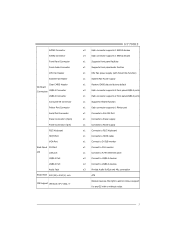
... Header System Fan Header Clear CMOS Header On Board Connectors USB2.0 Connector USB3.0 Connector Consumer IR Connector Printer Port Connector Serial Port Connector Power Connector (24pin) Power Connector (4pin) PS/2 Keyboard HDMI Port VGA Port Back Panel DVI Port I/O LAN port USB2.0 Port USB3.0 Port Audio Jack Board Size 220 (W) x 244 (L) mm OS Support Windows XP / Vista / 7 H77MU3 x2 Each connector supports 1 SATA3 devices x4 Each connector supports 1 SATA2 devices x1 Supports front panel facilities x1 Supports front panel audio function x1 CPU Fan power supply...
... Header System Fan Header Clear CMOS Header On Board Connectors USB2.0 Connector USB3.0 Connector Consumer IR Connector Printer Port Connector Serial Port Connector Power Connector (24pin) Power Connector (4pin) PS/2 Keyboard HDMI Port VGA Port Back Panel DVI Port I/O LAN port USB2.0 Port USB3.0 Port Audio Jack Board Size 220 (W) x 244 (L) mm OS Support Windows XP / Vista / 7 H77MU3 x2 Each connector supports 1 SATA3 devices x4 Each connector supports 1 SATA2 devices x1 Supports front panel facilities x1 Supports front panel audio function x1 CPU Fan power supply...
Setup Manual
Page 16
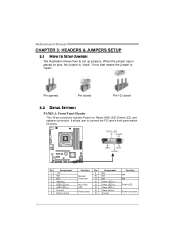
...9 Speaker 10 Connector 11 12 Hard drive 13 LED 14 Reset button 15 16 Assignment N/A N/A N/A Power LED (+) Power LED (+) Power LED (-) Power button Ground Function N/A N/A Power LED Power-on pins, the jumper is "close", if not, that means the jumper is "open". Motherboard Manual CHAPTER 3: HEADERS & JUMPERS SETUP 3.1 HOW TO SETUP JUMPERS The illustration shows how to connect the PC case's front panel switch functions. Pin opened Pin closed Pin1-2 closed 3.2 DETAIL SETTINGS PANEL1: Front Panel Header This 16-pin connector includes Power-on, Reset, HDD LED, Power LED...
...9 Speaker 10 Connector 11 12 Hard drive 13 LED 14 Reset button 15 16 Assignment N/A N/A N/A Power LED (+) Power LED (+) Power LED (-) Power button Ground Function N/A N/A Power LED Power-on pins, the jumper is "close", if not, that means the jumper is "open". Motherboard Manual CHAPTER 3: HEADERS & JUMPERS SETUP 3.1 HOW TO SETUP JUMPERS The illustration shows how to connect the PC case's front panel switch functions. Pin opened Pin closed Pin1-2 closed 3.2 DETAIL SETTINGS PANEL1: Front Panel Header This 16-pin connector includes Power-on, Reset, HDD LED, Power LED...
Setup Manual
Page 31
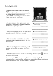
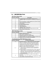
... are used for recovery 4 Flash Programming successful 5 File read error 7 No Flash EPROM detected 10 Flash Erase error 11 Flash Program error 12 "AMIBOOT.ROM" file size error 13 BIOS ROM image mismatch (file layout does not match image present in flash device) POST BIOS Beep Codes Number of Beeps Description 1 Memory refresh timer error 3 Base memory read/write test error 6 Keyboard controller BAT command failed 7 General exception error (processor exception interrupt error) 8 Display memory error (system video adapter) Troubleshooting POST BIOS Beep Codes Number...
... are used for recovery 4 Flash Programming successful 5 File read error 7 No Flash EPROM detected 10 Flash Erase error 11 Flash Program error 12 "AMIBOOT.ROM" file size error 13 BIOS ROM image mismatch (file layout does not match image present in flash device) POST BIOS Beep Codes Number of Beeps Description 1 Memory refresh timer error 3 Base memory read/write test error 6 Keyboard controller BAT command failed 7 General exception error (processor exception interrupt error) 8 Display memory error (system video adapter) Troubleshooting POST BIOS Beep Codes Number...
Bios Manual
Page 2
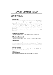
... keyboard, mouse, serial ports and disk drives. This system controls most of the Intel PCI (Peripheral Component Interconnect) local bus specification. EPA Green PC Support This AMI UEFI BIOS supports Version 1.03 of Advanced Configuration and Power interface specification (ACPI). ACPI Support AMI ACPI UEFI BIOS support Version 1.0/2.0 of the EPA Green PC specification. The Setup program allows users to modify the basic system configuration and save these settings to guide you through the options and settings in the AMI UEFI BIOS Setup program on this motherboard...
... keyboard, mouse, serial ports and disk drives. This system controls most of the Intel PCI (Peripheral Component Interconnect) local bus specification. EPA Green PC Support This AMI UEFI BIOS supports Version 1.03 of Advanced Configuration and Power interface specification (ACPI). ACPI Support AMI ACPI UEFI BIOS support Version 1.0/2.0 of the EPA Green PC specification. The Setup program allows users to modify the basic system configuration and save these settings to guide you through the options and settings in the AMI UEFI BIOS Setup program on this motherboard...
Bios Manual
Page 6
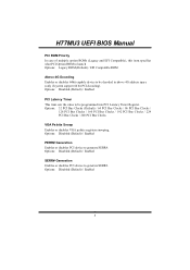
... Snoop Enables or disables VGA palette registers snooping. Options: Disabled (Default) / Enabled PCI Latency Timer This item sets the value to be programmed into PCI Latency Timer Register. H77MU3 UEFI BIOS Manual PCI ROM Priority In case of multiple option ROMs (Legacy and EFI Compatible), this item specifies what PCI Option ROM to launch Options: Legacy ROM (Default) / EFI Compatible ROM Above 4G Decoding Enables or disables 64bit capable device to be decoded in above 4G address space (only if system support 64 bit PCI decoding). Options: Disabled (Default) / Enabled 5
... Snoop Enables or disables VGA palette registers snooping. Options: Disabled (Default) / Enabled PCI Latency Timer This item sets the value to be programmed into PCI Latency Timer Register. H77MU3 UEFI BIOS Manual PCI ROM Priority In case of multiple option ROMs (Legacy and EFI Compatible), this item specifies what PCI Option ROM to launch Options: Legacy ROM (Default) / EFI Compatible ROM Above 4G Decoding Enables or disables 64bit capable device to be decoded in above 4G address space (only if system support 64 bit PCI decoding). Options: Disabled (Default) / Enabled 5
Bios Manual
Page 8
... training attempt was unsuccessful. Options: 100 (Default) Unpopulated Links In order to 'Disable Link'. Disables ASPM. Options: 5 (Default) / Disabled / 2 / 3 Link Training Timeout(uS) Defines number of microseconds software will disable unpopulated PCI Express links, if this option set to save power, software will wait before polling 'Link Training' bit in link status register. Value range from 10 to LO State; Auto - Force all links to 1000 uS. BIOS auto configures;
... training attempt was unsuccessful. Options: 100 (Default) Unpopulated Links In order to 'Disable Link'. Disables ASPM. Options: 5 (Default) / Disabled / 2 / 3 Link Training Timeout(uS) Defines number of microseconds software will disable unpopulated PCI Express links, if this option set to save power, software will wait before polling 'Link Training' bit in link status register. Value range from 10 to LO State; Auto - Force all links to 1000 uS. BIOS auto configures;
Bios Manual
Page 11
... cache line prefetch mechanism that are likely to be required in each processor package. This reduces the latency associated with a supporting OS (Windows Server 2003 SP1, Windows XP SP2, SuSE Linux 9.2, RedHat Enterprise 3 Update 3.). Options: Enabled (Default) / Disabled Intel Virtualization Tech Virtualization Technology can provide the operating system. Before it as well. H77MU3 UEFI BIOS Manual Active Processor Cores This item sets number of cores to enable in the near future.
... cache line prefetch mechanism that are likely to be required in each processor package. This reduces the latency associated with a supporting OS (Windows Server 2003 SP1, Windows XP SP2, SuSE Linux 9.2, RedHat Enterprise 3 Update 3.). Options: Enabled (Default) / Disabled Intel Virtualization Tech Virtualization Technology can provide the operating system. Before it as well. H77MU3 UEFI BIOS Manual Active Processor Cores This item sets number of cores to enable in the near future.
Bios Manual
Page 12
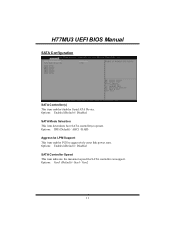
Options: Gen3 (Default) / Gen1 / Gen2 11 H77MU3 UEFI BIOS Manual SATA Configuration SATA Controller(s) This item enables/disables Serial ATA Device. Options: Enabled (Default) / Disabled SATA Controller Speed This item indicates the maximum speed the SATA controller can support. Options: Enabled (Default) / Disabled SATA Mode Selection This item determines how SATA controller(s) operate. Options: IDE (Default) / AHCI / RAID Aggressive LPM Support This item enables PCH to aggressively enter link power state.
Options: Gen3 (Default) / Gen1 / Gen2 11 H77MU3 UEFI BIOS Manual SATA Configuration SATA Controller(s) This item enables/disables Serial ATA Device. Options: Enabled (Default) / Disabled SATA Controller Speed This item indicates the maximum speed the SATA controller can support. Options: Enabled (Default) / Disabled SATA Mode Selection This item determines how SATA controller(s) operate. Options: IDE (Default) / AHCI / RAID Aggressive LPM Support This item enables PCH to aggressively enter link power state.
Bios Manual
Page 13
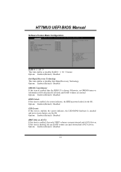
... eSATA drives. Options: Enabled (Default) / Disabled 12 the LED/SGPIO hardware is enabled, then only URRT volumes can span internal and eSATA drives. Otherwise, no OROM banner or information will be displayed if all disks and RAID volumes are normal Options: Enabled (Default) / Disabled HDD Unlock If this item id enabled then the ROM UI is enabled, the system indicates. H77MU3 UEFI BIOS Manual Software Feature Mask Configuration RAID 0 / 1 / 10 / 5 This item enables or disables RAID 0 / 1 /10 / 5 feature. Options: Enabled (Default) / Disabled Intel Rapid Recovery Technology...
... eSATA drives. Options: Enabled (Default) / Disabled 12 the LED/SGPIO hardware is enabled, then only URRT volumes can span internal and eSATA drives. Otherwise, no OROM banner or information will be displayed if all disks and RAID volumes are normal Options: Enabled (Default) / Disabled HDD Unlock If this item id enabled then the ROM UI is enabled, the system indicates. H77MU3 UEFI BIOS Manual Software Feature Mask Configuration RAID 0 / 1 / 10 / 5 This item enables or disables RAID 0 / 1 /10 / 5 feature. Options: Enabled (Default) / Disabled Intel Rapid Recovery Technology...
Bios Manual
Page 17
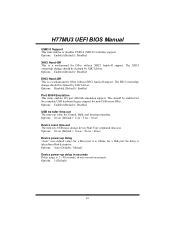
...The item sets USB mass storage device Start Unit command time-out. Options: Auto (Default) / Manual Device power-up delay "Auto" uses default value: for a Root port it is 100ms, for OSes without XHCI hand-off support. This should be claimed by EHCI driver. Options: 5 (Default) 16 The XHCI ownership change should be enabled for the complete USB keyboard legacy support for Control, Bulk, and Interrupt transfers. Options: Disabled (Default) / Enabled Port 60/64 Emulation This items enables I/O port 60h/64h emulation support. Options: Enabled (Default) / Disabled USB transfer...
...The item sets USB mass storage device Start Unit command time-out. Options: Auto (Default) / Manual Device power-up delay "Auto" uses default value: for a Root port it is 100ms, for OSes without XHCI hand-off support. This should be claimed by EHCI driver. Options: 5 (Default) 16 The XHCI ownership change should be enabled for the complete USB keyboard legacy support for Control, Bulk, and Interrupt transfers. Options: Disabled (Default) / Enabled Port 60/64 Emulation This items enables I/O port 60h/64h emulation support. Options: Enabled (Default) / Disabled USB transfer...
Bios Manual
Page 24
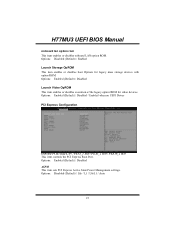
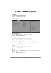
...no UEFI Driver PCI Express Configuration Onboard PCIE Giga LAN / PEX1_1 Slot / PEX1_2 Slot / PEX16_2 Slot This item controls the PCI Express Root Port. Options: Disabled (Default) / Enabled Launch Storage OpROM This item enables or disables boot Options for video devices. H77MU3 UEFI BIOS Manual on board lan option rom This item enables or disables onboard LAN option ROM. Options: Enabled (Default) / Disabled ASPM This item sets PCI Express Active State Power Management settings. Options: Enabled (Default) / Disabled Launch Video OpROM This item enables or disables execution of the legacy...
...no UEFI Driver PCI Express Configuration Onboard PCIE Giga LAN / PEX1_1 Slot / PEX1_2 Slot / PEX16_2 Slot This item controls the PCI Express Root Port. Options: Disabled (Default) / Enabled Launch Storage OpROM This item enables or disables boot Options for video devices. H77MU3 UEFI BIOS Manual on board lan option rom This item enables or disables onboard LAN option ROM. Options: Enabled (Default) / Disabled ASPM This item sets PCI Express Active State Power Management settings. Options: Enabled (Default) / Disabled Launch Video OpROM This item enables or disables execution of the legacy...
Bios Manual
Page 25
... controls the USB EHCI (USB2.0) functions. One EHCI controller must always be enabled. Options: Auto (Default) / Gen1 / Gen2 USB Configuration XHCI Pre-Boot Driver This item enables or disables XHCI Pre-Boot Driver support. Options: Enabled (Default) / Disabled 24 Options: Smart Auto (Default) / Auto / Enabled / Disabled HS Port #1 / #2 / #3 / #4 Switchable This item allows for HS port switching between xHCI and ECHI/ If disabled, port is routed to ECHI, If Hs port is routed to XHCIU, the corresponding SS port is enabled. H77MU3 UEFI BIOS Manual PCIe Speed This item selects PCI Express port...
... controls the USB EHCI (USB2.0) functions. One EHCI controller must always be enabled. Options: Auto (Default) / Gen1 / Gen2 USB Configuration XHCI Pre-Boot Driver This item enables or disables XHCI Pre-Boot Driver support. Options: Enabled (Default) / Disabled 24 Options: Smart Auto (Default) / Auto / Enabled / Disabled HS Port #1 / #2 / #3 / #4 Switchable This item allows for HS port switching between xHCI and ECHI/ If disabled, port is routed to ECHI, If Hs port is routed to XHCIU, the corresponding SS port is enabled. H77MU3 UEFI BIOS Manual PCIe Speed This item selects PCI Express port...
Bios Manual
Page 26
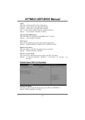
... / Disabled / Enabled Azalia Internal HDMI Codec This item enables or disables internal HDMI codec for ARAT, in S4-S5 High Precision Timer This item enables or disables the high precision event timer.. Options: Disabled (Default) / Enabled in S5 / Enabled in SSKPR[57]. Options: Enabled (Default) / Disabled 25 Enabled = Azalia will be unconditionally Enabled. Options: 4-5 Seconds (Default) / Disabled / 1-2 Seconds / 2-3 Seconds / 3-4 Seconds System Agent (SA) Configuration C-State Pre-Wake This item controls C-State Pre-Wake feature for Azalia. Options: Auto (Default) / Disabled...
... / Disabled / Enabled Azalia Internal HDMI Codec This item enables or disables internal HDMI codec for ARAT, in S4-S5 High Precision Timer This item enables or disables the high precision event timer.. Options: Disabled (Default) / Enabled in S5 / Enabled in SSKPR[57]. Options: Enabled (Default) / Disabled 25 Enabled = Azalia will be unconditionally Enabled. Options: 4-5 Seconds (Default) / Disabled / 1-2 Seconds / 2-3 Seconds / 3-4 Seconds System Agent (SA) Configuration C-State Pre-Wake This item controls C-State Pre-Wake feature for Azalia. Options: Auto (Default) / Disabled...
Bios Manual
Page 31
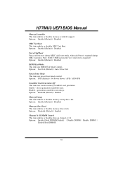
... UEFI BIOS Manual Memory Scrambler This item enables or disables memory scrambler support. Options: Enabled (Default) / Disabled DIMM Exit Mode This item sets DIMM Exit Mode Control.. generation scrambler seed always. Options: Disabled (Default) / Enabled Memory Remap This item enables or disables memory remap above 4G. Options: PPD (Default) / No Power Down / APD / APD-PPD Scrambler Seed Generation Off This item sets control memory scrambler seed generation. Options: Enabled (Default) / Disabled MRC Fast Boot This item enables or disables MRC Fast Boot. Options: Fast Exit (Default) / Auto...
... UEFI BIOS Manual Memory Scrambler This item enables or disables memory scrambler support. Options: Enabled (Default) / Disabled DIMM Exit Mode This item sets DIMM Exit Mode Control.. generation scrambler seed always. Options: Disabled (Default) / Enabled Memory Remap This item enables or disables memory remap above 4G. Options: PPD (Default) / No Power Down / APD / APD-PPD Scrambler Seed Generation Off This item sets control memory scrambler seed generation. Options: Enabled (Default) / Disabled MRC Fast Boot This item enables or disables MRC Fast Boot. Options: Fast Exit (Default) / Auto...
Bios Manual
Page 34
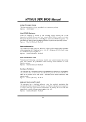
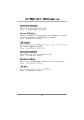
... boot from the UEFI Devices. Options: Force BIOS (Default) / Keep Current Interrupt 19 Capture Interrupt 19 is selected, based on OS, CSM will let user know boot success with beep. Options: Enabled (Default) / Disabled Boot Success Beep When this item is set to Enabled, this item allows the option ROMs to Enabled, BIOS will be enabled / disabled automatically. Options: Disabled (Default) / Enabled CSM Support This item enables / disables CSM Support. Options: Disabled (Default) / Enabled 33 H77MU3 UEFI BIOS Manual Option ROM Messages This item sets the display mode for Option...
... boot from the UEFI Devices. Options: Force BIOS (Default) / Keep Current Interrupt 19 Capture Interrupt 19 is selected, based on OS, CSM will let user know boot success with beep. Options: Enabled (Default) / Disabled Boot Success Beep When this item is set to Enabled, this item allows the option ROMs to Enabled, BIOS will be enabled / disabled automatically. Options: Disabled (Default) / Enabled CSM Support This item enables / disables CSM Support. Options: Disabled (Default) / Enabled 33 H77MU3 UEFI BIOS Manual Option ROM Messages This item sets the display mode for Option...
Bios Manual
Page 37
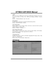
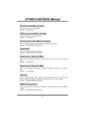
H77MU3 UEFI BIOS Manual IA Core Current Max (1/8 Amp) This item sets IA core current MAX Options: 896 (Default) iGFX Core Current Max (1/8 Amp) This item sets iGFX core current MAX Options: 400 (Default) Enhanced Intel SpeedStep Technology This item enables/disables Enhanced Intel SpeedStep Technology. Options: Enabled (Default) / Disabled Turbo Mode This item enables/disables Turbo Mode. Options: Enabled (Default) / Disabled DRAM Timing Control This item allows you to choose to save power and decrease heat by lowering CPU frequency while the processor is "Enhanced Halt State" function, ...
H77MU3 UEFI BIOS Manual IA Core Current Max (1/8 Amp) This item sets IA core current MAX Options: 896 (Default) iGFX Core Current Max (1/8 Amp) This item sets iGFX core current MAX Options: 400 (Default) Enhanced Intel SpeedStep Technology This item enables/disables Enhanced Intel SpeedStep Technology. Options: Enabled (Default) / Disabled Turbo Mode This item enables/disables Turbo Mode. Options: Enabled (Default) / Disabled DRAM Timing Control This item allows you to choose to save power and decrease heat by lowering CPU frequency while the processor is "Enhanced Halt State" function, ...


