
Setup Manual
Page 3
... parts inside ) FDD Cable X 1 (optional) USB 2.0 Cable X1 (optional) Serial ATA Power Cable X 1 (optional) Note: The package contents may be different due to area or your motherboard version. 1 Before you start installing the motherboard, please make sure you follow the instructions below: „ Prepare a dry and stable working environment with sufficient lighting. „ Always disconnect the computer from power outlet before operation. „ Before you for ATX Case X 1 Installation Guide X 1 Fully Setup Driver CD X 1 (full version manual files...
... parts inside ) FDD Cable X 1 (optional) USB 2.0 Cable X1 (optional) Serial ATA Power Cable X 1 (optional) Note: The package contents may be different due to area or your motherboard version. 1 Before you start installing the motherboard, please make sure you follow the instructions below: „ Prepare a dry and stable working environment with sufficient lighting. „ Always disconnect the computer from power outlet before operation. „ Before you for ATX Case X 1 Installation Guide X 1 Fully Setup Driver CD X 1 (full version manual files...
Setup Manual
Page 4
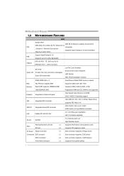
... Chipset Max Shared Video Memory is 512MB DX10 / HDCP / PureVideo support IDE Integrated IDE Controller Ultra DMA 33 / 66 / 100 / 133 Bus Master Mode supports PIO Mode 0~4, SATA II Integrated Serial ATA Controller Data transfer rates up to 3 Gb/s SATA Version 2.0 specification compliant LAN Realtek RTL 8201CL PHY 10 / 100 Mb/s auto negotiation Half / Full duplex capability Sound ALC662 5.1 channels audio out High Definition Audio Slots PCI Express Gen2 x16 slot PCI slot x1 Supports PCI-E Gen2 x16 expansion cards x2 Supports PCI expansion cards On Board Floppy Connector...
... Chipset Max Shared Video Memory is 512MB DX10 / HDCP / PureVideo support IDE Integrated IDE Controller Ultra DMA 33 / 66 / 100 / 133 Bus Master Mode supports PIO Mode 0~4, SATA II Integrated Serial ATA Controller Data transfer rates up to 3 Gb/s SATA Version 2.0 specification compliant LAN Realtek RTL 8201CL PHY 10 / 100 Mb/s auto negotiation Half / Full duplex capability Sound ALC662 5.1 channels audio out High Definition Audio Slots PCI Express Gen2 x16 slot PCI slot x1 Supports PCI-E Gen2 x16 expansion cards x2 Supports PCI expansion cards On Board Floppy Connector...
Setup Manual
Page 5
... M2+ TE/GF8200C M2+ SPEC Front Audio Connector x1 Supports front panel audio function CD-in Connector x1 Supports CD audio-in function CPU Fan Header x1 CPU Fan power supply (with Smart Fan function) System Fan Header x1 System Fan Power supply CMOS clear Header x1 Restore CMOS data to factory default USB Connector x3 Each connector supports 2 front panel USB ports Power Connector (24pin) x1 Connects to Power supply Power Connector (4pin) x1 Connects to Power supply Printer Port Connector x1 Each connector supports 1 Printer port Serial port Connector x1 Connects...
... M2+ TE/GF8200C M2+ SPEC Front Audio Connector x1 Supports front panel audio function CD-in Connector x1 Supports CD audio-in function CPU Fan Header x1 CPU Fan power supply (with Smart Fan function) System Fan Header x1 System Fan Power supply CMOS clear Header x1 Restore CMOS data to factory default USB Connector x3 Each connector supports 2 front panel USB ports Power Connector (24pin) x1 Connects to Power supply Power Connector (4pin) x1 Connects to Power supply Printer Port Connector x1 Each connector supports 1 Printer port Serial port Connector x1 Connects...
Setup Manual
Page 12
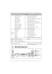
This connector supports the provided floppy drive ribbon cable. 2 34 1 33 IDE: IDE/ATAPI Connector The motherboard has a 32-bit Enhanced PCI IDE Controller that supports 360K, 720K, 1.2M, 1.44M and 2.88M floppy disk types. Motherboard Manual 2.4 CONNECTORS AND SLOTS FDD: Floppy Disk Connector The motherboard provides a standard floppy disk connector that provides PIO Mode 0~4, Bus Master, and Ultra DMA 33/66/100/133 functionality. The IDE connector can connect a master and a slave drive, so you can connect up to two drives. 40 39 21 10
This connector supports the provided floppy drive ribbon cable. 2 34 1 33 IDE: IDE/ATAPI Connector The motherboard has a 32-bit Enhanced PCI IDE Controller that supports 360K, 720K, 1.2M, 1.44M and 2.88M floppy disk types. Motherboard Manual 2.4 CONNECTORS AND SLOTS FDD: Floppy Disk Connector The motherboard provides a standard floppy disk connector that provides PIO Mode 0~4, Bus Master, and Ultra DMA 33/66/100/133 functionality. The IDE connector can connect a master and a slave drive, so you can connect up to two drives. 40 39 21 10
Setup Manual
Page 14
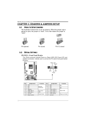
...6 HDD LED (-) 7 Ground 8 Reset control Function Pin 9 Speaker 10 Connector 11 12 Hard drive 13 LED 14 Reset button 15 16 Assignment N/A N/A N/A Power LED (+) Power LED (+) Power LED (-) Power button Ground Function N/A N/A Power LED Power-on , Reset, HDD LED, Power LED, and speaker connection. Motherboard Manual CHAPTER 3: HEADERS & JUMPERS SETUP 3.1 HOW TO SETUP JUMPERS The illustration shows how to connect the PC case's front panel switch functions. When the jumper cap is placed on pins, the jumper is "close", if not, that means the jumper is "open". It allows user to set...
...6 HDD LED (-) 7 Ground 8 Reset control Function Pin 9 Speaker 10 Connector 11 12 Hard drive 13 LED 14 Reset button 15 16 Assignment N/A N/A N/A Power LED (+) Power LED (+) Power LED (-) Power button Ground Function N/A N/A Power LED Power-on , Reset, HDD LED, Power LED, and speaker connection. Motherboard Manual CHAPTER 3: HEADERS & JUMPERS SETUP 3.1 HOW TO SETUP JUMPERS The illustration shows how to connect the PC case's front panel switch functions. When the jumper cap is placed on pins, the jumper is "close", if not, that means the jumper is "open". It allows user to set...
Setup Manual
Page 27
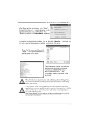
... including motherboard/BIOS/CPU/video/ device/OS information. Open the saved .txt file, you will not share customer's data with other third parties, so please feel free to provide your system information while using Outlook Express as ...file to our tech support with any other e-mail application. GF8100 M2+ TE/GF8200C M2+ After filling up this information to a .txt file, click "Save As..." If you are not using eHot-Line service. Go to the following web http://www.biostar.com.tw/app/en-us/about/contact.php for your default e-mail client application, you to enter file...
... including motherboard/BIOS/CPU/video/ device/OS information. Open the saved .txt file, you will not share customer's data with other third parties, so please feel free to provide your system information while using Outlook Express as ...file to our tech support with any other e-mail application. GF8100 M2+ TE/GF8200C M2+ After filling up this information to a .txt file, click "Save As..." If you are not using eHot-Line service. Go to the following web http://www.biostar.com.tw/app/en-us/about/contact.php for your default e-mail client application, you to enter file...
Setup Manual
Page 30
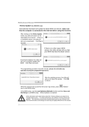
... BIOS version, the utility will ask you to reboot the system. All the information and content above are subject to the internet before using this manual. 28 After the updating process, the utility will ask you to download it. Click Yes to enter BIOS setup. Motherboard Manual (for your BIOS has been the latest version. While the system boots up and the full screen logo shows, press key...
... BIOS version, the utility will ask you to reboot the system. All the information and content above are subject to the internet before using this manual. 28 After the updating process, the utility will ask you to download it. Click Yes to enter BIOS setup. Motherboard Manual (for your BIOS has been the latest version. While the system boots up and the full screen logo shows, press key...
Setup Manual
Page 32
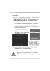
... Power-On Self Tests (POST) procedure while booting up. The utility will ask you an easy and simple way to the USB port or the floppy disk drive. 4. z This utility only allows storage device with BIO-Flasher 1. Motherboard Manual BIO-Flasher BIO-Flasher is built in the BIOS chip. The BIO-Flasher is a BIOS flashing utility providing you to enter the utility. 5. Insert the USB pen drive or the floppy disk that contains the BIOS file to update your BIOS via USB pen drive or floppy disk...
... Power-On Self Tests (POST) procedure while booting up. The utility will ask you an easy and simple way to the USB port or the floppy disk drive. 4. z This utility only allows storage device with BIO-Flasher 1. Motherboard Manual BIO-Flasher BIO-Flasher is built in the BIOS chip. The BIO-Flasher is a BIOS flashing utility providing you to enter the utility. 5. Insert the USB pen drive or the floppy disk that contains the BIOS file to update your BIOS via USB pen drive or floppy disk...
Setup Manual
Page 33
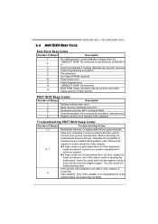
... 7 cards are used for recovery 4 Flash Programming successful 5 File read error 7 No Flash EPROM detected 10 Flash Erase error 11 Flash Program error 12 "AMIBOOT.ROM" file size error 13 BIOS ROM image mismatch (file layout does not match image present in flash device) POST BIOS Beep Codes Number of Beeps Description 1 Memory refresh timer error 3 Base memory read/write test error 6 Keyboard controller BAT command failed 7 General exception error (processor exception interrupt error) 8 Display memory error (system video adapter) Troubleshooting POST BIOS Beep Codes...
... 7 cards are used for recovery 4 Flash Programming successful 5 File read error 7 No Flash EPROM detected 10 Flash Erase error 11 Flash Program error 12 "AMIBOOT.ROM" file size error 13 BIOS ROM image mismatch (file layout does not match image present in flash device) POST BIOS Beep Codes Number of Beeps Description 1 Memory refresh timer error 3 Base memory read/write test error 6 Keyboard controller BAT command failed 7 General exception error (processor exception interrupt error) 8 Display memory error (system video adapter) Troubleshooting POST BIOS Beep Codes...
Setup Manual
Page 34
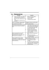
... for compatibility with other drives. 32 Motherboard Manual 5.5 TROUBLESHOOTING Probable Solution 1. fan of are running from a hard disk. Replace cable. System is Power LED does not shine; System only boots from a hard disk 1. Review system's equipment. Run SETUP program and select correct drive types. Make sure power cable is inoperative. the securely plugged in the standard CMOS setup. 2. Back up the hard drive is extremely important. work 3. fails to boot from disk to disk controller board. System cannot boot after user installs...
... for compatibility with other drives. 32 Motherboard Manual 5.5 TROUBLESHOOTING Probable Solution 1. fan of are running from a hard disk. Replace cable. System is Power LED does not shine; System only boots from a hard disk 1. Review system's equipment. Run SETUP program and select correct drive types. Make sure power cable is inoperative. the securely plugged in the standard CMOS setup. 2. Back up the hard drive is extremely important. work 3. fails to boot from disk to disk controller board. System cannot boot after user installs...
Bios Setup
Page 2
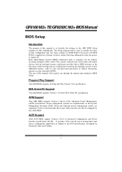
... y Support T his system controls most of the input and output devices such as keyboard, mouse, serial ports and disk drives. GF8100 M2+ TE/GF8200C M2+ BIOSManual BIOS Setup Introduction T he purpose of this manual is turned off. APM Support T his AMI BIOS supports Version 1.03 of the EPA Green PC specification. Power to describe the settings in BIOS Setup. T he rest of the Advanced Power Management (APM) speci fication. ACPI Support AMI ACPI BIOS support Version 1.0/2.0 of CMOS RAM is supplied by this motherboard. The Setup...
... y Support T his system controls most of the input and output devices such as keyboard, mouse, serial ports and disk drives. GF8100 M2+ TE/GF8200C M2+ BIOSManual BIOS Setup Introduction T he purpose of this manual is turned off. APM Support T his AMI BIOS supports Version 1.03 of the EPA Green PC specification. Power to describe the settings in BIOS Setup. T he rest of the Advanced Power Management (APM) speci fication. ACPI Support AMI ACPI BIOS support Version 1.0/2.0 of CMOS RAM is supplied by this motherboard. The Setup...
Bios Setup
Page 5
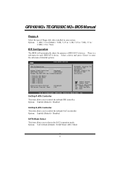
... IDE Controller. GF8100 M2+ TE/GF8200C M2+ BIOSManual Floppy A Select the type of ID E/SAT A devices. Options: 1.44M, 3.5 in (Default) / 360K, 5.25 in / 1.2M, 5.25 in / 720K, 3.5 in / 2.88M, 3.5 in / None IDE Configuration T he BIOS will automatically detect the presence of floppy disk drive installed in your system. OnChip P-ATA C ontroller T his item allows you to control the onboard SAT A controller. Options: Enabled (Default) / Disabled OnChip S-ATA C ontroller T his item allows you to control the onboard IDE controller. Options: Enabled (Default) / Disabled SATA Mode...
... IDE Controller. GF8100 M2+ TE/GF8200C M2+ BIOSManual Floppy A Select the type of ID E/SAT A devices. Options: 1.44M, 3.5 in (Default) / 360K, 5.25 in / 1.2M, 5.25 in / 720K, 3.5 in / 2.88M, 3.5 in / None IDE Configuration T he BIOS will automatically detect the presence of floppy disk drive installed in your system. OnChip P-ATA C ontroller T his item allows you to control the onboard SAT A controller. Options: Enabled (Default) / Disabled OnChip S-ATA C ontroller T his item allows you to control the onboard IDE controller. Options: Enabled (Default) / Disabled SATA Mode...
Bios Setup
Page 6
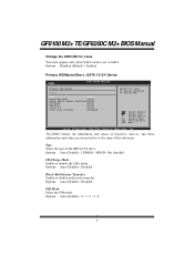
...GF8200C M2+ BIOSManual Change the AHCI DID for Linux T his item appears only when SAT A mode is set to the name of the sub-menu. SATA 1/2/3/4 Device Main BIOS SETUP UTILITY Primary IDE Master Device : Type [Auto] LBA/Large Mode [Auto] Block (Multi-Sector Transfer)[Auto] PIO Mode [Auto] DMA Mode [Auto] S.M.A.R.T [Auto] 32Bit Data Transfer [Enabled] Select the type of the IDE/SAT A drive. Select Screen Select Item +- Options: Auto (Default) / Disabled PIO Mode Select the PIO mode. Options: Auto (Default) / CDROM / ARMD / Not Installed LBA/Large Mode Enable or disable...
...GF8200C M2+ BIOSManual Change the AHCI DID for Linux T his item appears only when SAT A mode is set to the name of the sub-menu. SATA 1/2/3/4 Device Main BIOS SETUP UTILITY Primary IDE Master Device : Type [Auto] LBA/Large Mode [Auto] Block (Multi-Sector Transfer)[Auto] PIO Mode [Auto] DMA Mode [Auto] S.M.A.R.T [Auto] 32Bit Data Transfer [Enabled] Select the type of the IDE/SAT A drive. Select Screen Select Item +- Options: Auto (Default) / Disabled PIO Mode Select the PIO mode. Options: Auto (Default) / CDROM / ARMD / Not Installed LBA/Large Mode Enable or disable...
Bios Setup
Page 8
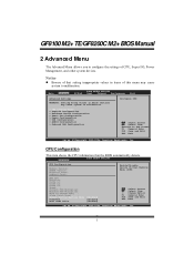
... > Hardware Hea lth Configuration > Smart Fan Co nfiguration > Power Config uration > USB Configur ation > AUDIO Config uration > Onboard LAN Configuration Configure CPU. S elect Screen S elect Item EnterG o to Change Freq : uCode Patch Le vel : Secure Virtual Machine Mode PowerNow ACPI SRAT Tabl e [Ena bled] [Ena bled] [Ena bled] S elect Screen S elect Item +- Advan ced BIOS SETU P U TILITY CPU Configurat ion Module Version : AGESA Version: Physical Count : Logical Count: Enable/Disable Secure Virtual Machine Mode (SVM) AMD CPU Revision: Cache L1...
... > Hardware Hea lth Configuration > Smart Fan Co nfiguration > Power Config uration > USB Configur ation > AUDIO Config uration > Onboard LAN Configuration Configure CPU. S elect Screen S elect Item EnterG o to Change Freq : uCode Patch Le vel : Secure Virtual Machine Mode PowerNow ACPI SRAT Tabl e [Ena bled] [Ena bled] [Ena bled] S elect Screen S elect Item +- Advan ced BIOS SETU P U TILITY CPU Configurat ion Module Version : AGESA Version: Physical Count : Logical Count: Enable/Disable Secure Virtual Machine Mode (SVM) AMD CPU Revision: Cache L1...
Bios Setup
Page 9
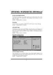
Options: Enabled (Default) / Disabled SuperIO Configuration Advan ced BIOS SETU P U TILITY Configure ITE8 718 Super IO Chipse t Onboard Floppy Controller Serial Port1 A ddress Parallel Port Address Parallel Por t Mode Parallel Por t IRQ Keyboard Power On Mouse PowerOn Restore on the system board and you wish to use it. T his item allows you installed another FDC or the system uses no floppy drive, select disabled in this field. C hange Option F1 G eneral Help F10 S ave...
Options: Enabled (Default) / Disabled SuperIO Configuration Advan ced BIOS SETU P U TILITY Configure ITE8 718 Super IO Chipse t Onboard Floppy Controller Serial Port1 A ddress Parallel Port Address Parallel Por t Mode Parallel Por t IRQ Keyboard Power On Mouse PowerOn Restore on the system board and you wish to use it. T his item allows you installed another FDC or the system uses no floppy drive, select disabled in this field. C hange Option F1 G eneral Help F10 S ave...
Bios Setup
Page 14
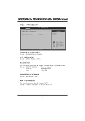
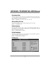
bits] Options Disabled Enabled S elect Screen S elect Item +- SouthBridge ACPI HPET TABLE Options: Enabled (Default) / Disabled ACPI PM Timer Width Options: 24-bits (Default) / 32-bits Suspend mode T he item allows you to select the version of ACPI. Options: ACPI v1.0 (Default) / ACPI v2.0 / ACPI v3.0 13 Options: S1 (POS) (Default) Power on Suspend S3 (ST R) Suspend to RAM Auto POS+STR Repost Video on S3 Resume Options: NO (Default) / YES ACPI Version Features T he item allows you to select the suspend type under the...
bits] Options Disabled Enabled S elect Screen S elect Item +- SouthBridge ACPI HPET TABLE Options: Enabled (Default) / Disabled ACPI PM Timer Width Options: 24-bits (Default) / 32-bits Suspend mode T he item allows you to select the version of ACPI. Options: ACPI v1.0 (Default) / ACPI v2.0 / ACPI v3.0 13 Options: S1 (POS) (Default) Power on Suspend S3 (ST R) Suspend to RAM Auto POS+STR Repost Video on S3 Resume Options: NO (Default) / YES ACPI Version Features T he item allows you to select the suspend type under the...
Bios Setup
Page 17
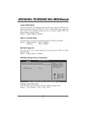
... legacy support fo r USB devices like the keyboard, mouse, and USB drive. Options: Enabled (Default) / Disabled USB Mass Storage Dev ice Configuration Advanced BIOS SETUP UTILITY USB Mass Storage Device Configuration USB Mass Storage Reset Delay [20 Sec] Device # Emulation Type [Auto] Number of the USB 2.0 controller. Change Option F1 General Help F10 Save and Exit ESC Exit vxx.xx (C)Copyright 1985-200x, American Megatrends, Inc. Options: 20 Sec (Default) / 10 Sec / 30 Sec / 40 Sec 16 Microso ft DOS or Windows NT). Select Screen...
... legacy support fo r USB devices like the keyboard, mouse, and USB drive. Options: Enabled (Default) / Disabled USB Mass Storage Dev ice Configuration Advanced BIOS SETUP UTILITY USB Mass Storage Device Configuration USB Mass Storage Reset Delay [20 Sec] Device # Emulation Type [Auto] Number of the USB 2.0 controller. Change Option F1 General Help F10 Save and Exit ESC Exit vxx.xx (C)Copyright 1985-200x, American Megatrends, Inc. Options: 20 Sec (Default) / 10 Sec / 30 Sec / 40 Sec 16 Microso ft DOS or Windows NT). Select Screen...

Bios Setup
Page 19
...Me gatrends, Inc. Options: Auto (Default) / Disabled Onbaord Lan Boot ROM T his item allows you to enable or disable the Onboard LAN Boot ROM. Options: Disabled (Default) / Enabled MAC ID Information T his option allows you to control the onboard LAN controller. Onboard LAN T his item shows the LAN MAC ID information. 18 GF8100 M2+ TE/GF8200C M2+ BIOSManual Onboard LAN Configuration Advan ced BIOS SETU P U TILITY Onboard LAN Co nfiguration Onboard LAN Onboard Lan Bo ot ROM MAC ID Informa tion : [Aut o] [Dis abled] Control onboard Lan on/off S elect Screen S elect Item +-
...Me gatrends, Inc. Options: Auto (Default) / Disabled Onbaord Lan Boot ROM T his item allows you to enable or disable the Onboard LAN Boot ROM. Options: Disabled (Default) / Enabled MAC ID Information T his option allows you to control the onboard LAN controller. Onboard LAN T his item shows the LAN MAC ID information. 18 GF8100 M2+ TE/GF8200C M2+ BIOSManual Onboard LAN Configuration Advan ced BIOS SETU P U TILITY Onboard LAN Co nfiguration Onboard LAN Onboard Lan Bo ot ROM MAC ID Informa tion : [Aut o] [Dis abled] Control onboard Lan on/off S elect Screen S elect Item +-
Bios Setup
Page 21
... PCI/PnP devices. Options: Enabled (Default) / Disabled PCI Resource BIOS SETUP UTILITY PCIPnP PCI Resource IRQ3 IRQ4 IRQ5 IRQ7 IRQ9 IRQ10 IRQ11 IRQ14 IRQ15 [Available] [Available] [Available] [Available] [Available] [Available] [Available] [Available] [Available] Available: Specified IRQ is available to be used by Legacy ISA devices. Reserved: Specified IRQ is a toggle for the built-in driver that allows the onbo ard ID E controller to perform DMA (Direct Memory Access...
... PCI/PnP devices. Options: Enabled (Default) / Disabled PCI Resource BIOS SETUP UTILITY PCIPnP PCI Resource IRQ3 IRQ4 IRQ5 IRQ7 IRQ9 IRQ10 IRQ11 IRQ14 IRQ15 [Available] [Available] [Available] [Available] [Available] [Available] [Available] [Available] [Available] Available: Specified IRQ is available to be used by Legacy ISA devices. Reserved: Specified IRQ is a toggle for the built-in driver that allows the onbo ard ID E controller to perform DMA (Direct Memory Access...
Bios Setup
Page 37
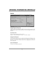
... from making changes using the CMOS Setup Utility. BIOS SETU P U TILITY Exit Security Setti ngs Supervisor Pas sword :Not Installe d User Password :Not Installe d Change Supervi sor Password User Access Le vel Change User Pa ssword Clear User Pas sword Password Check [Ful l Access] [Set up] Boot Sector Vi rus Protection [Dis abled] Install or Change the password. Options: Full Access (Default) / No Access / View Only / Limited Change User Password If the Supervisor Password is for clearing user passwo rd. 36 GF8100 M2+ TE/GF8200C M2+ BIOSManual Security...
... from making changes using the CMOS Setup Utility. BIOS SETU P U TILITY Exit Security Setti ngs Supervisor Pas sword :Not Installe d User Password :Not Installe d Change Supervi sor Password User Access Le vel Change User Pa ssword Clear User Pas sword Password Check [Ful l Access] [Set up] Boot Sector Vi rus Protection [Dis abled] Install or Change the password. Options: Full Access (Default) / No Access / View Only / Limited Change User Password If the Supervisor Password is for clearing user passwo rd. 36 GF8100 M2+ TE/GF8200C M2+ BIOSManual Security...


