Bios Setup
Page 2
...ports and disk drives. APM Support T his AMI BIOS supports Version 1.03 of the EPA Green PC specification. T he rest of this motherboard. The Setup program allows users to modify the basic system configuration and save these settings to CMOS RAM. Plug and Pla y Support T... AMI ACPI BIOS support Version 1.0/2.0 of Advanced Configuration and Power interface specifi cation (ACPI). Sleep and Suspend power man agement modes are supported. G41D3+/G41D3G+ BIOS M anual BIOS Setup Introduction T he purpose of this manual is turned off. BIOS activates at the first stag e o f...
...ports and disk drives. APM Support T his AMI BIOS supports Version 1.03 of the EPA Green PC specification. T he rest of this motherboard. The Setup program allows users to modify the basic system configuration and save these settings to CMOS RAM. Plug and Pla y Support T... AMI ACPI BIOS support Version 1.0/2.0 of Advanced Configuration and Power interface specifi cation (ACPI). Sleep and Suspend power man agement modes are supported. G41D3+/G41D3G+ BIOS M anual BIOS Setup Introduction T he purpose of this manual is turned off. BIOS activates at the first stag e o f...
Bios Setup
Page 3
G41D3+/G41D3G+ BIOS M anual PCI Bus Support T his AMI BIOS supports the Intel CPU. In the BIOS setup utility, you can use these keys to select ... settings to enter the BIOS setup utility. DRAM S upport DDR3 SDRAM (Double Data Rate III Synchronous DRAM) is being continuously updated. T he content of the motherboard. z For better system perform ance, the BIOS firmware is supported.
G41D3+/G41D3G+ BIOS M anual PCI Bus Support T his AMI BIOS supports the Intel CPU. In the BIOS setup utility, you can use these keys to select ... settings to enter the BIOS setup utility. DRAM S upport DDR3 SDRAM (Double Data Rate III Synchronous DRAM) is being continuously updated. T he content of the motherboard. z For better system perform ance, the BIOS firmware is supported.
Bios Setup
Page 15
Options: No (Default) / Yes ACPI Version Features T he item allows you to enable or disable the motherboard's APIC (Advan ced Programmable Interrupt Controller). Options: ACPI v1.0 (Default) / ACPI v2.0 / ACPI v3.0 ACPI APIC support T his is a server-speci fic feature. T he ... (Default) / Disabled AMI OEMB table Set this value to allow the ACPIBIOS to add a pointer to select the suspend type under the ACPI operating system. G41D3+/G41D3G+ BIOS M anual Suspend mode T he item allows you to an OEMB table in headless mode, both BIOS and operating system (e.g. Options: S1 (POS) (...
Options: No (Default) / Yes ACPI Version Features T he item allows you to enable or disable the motherboard's APIC (Advan ced Programmable Interrupt Controller). Options: ACPI v1.0 (Default) / ACPI v2.0 / ACPI v3.0 ACPI APIC support T his is a server-speci fic feature. T he ... (Default) / Disabled AMI OEMB table Set this value to allow the ACPIBIOS to add a pointer to select the suspend type under the ACPI operating system. G41D3+/G41D3G+ BIOS M anual Suspend mode T he item allows you to an OEMB table in headless mode, both BIOS and operating system (e.g. Options: S1 (POS) (...
Bios Setup
Page 16
G41D3+/G41D3G+ BIOS M anual USB Dev ice Wakeup from S3/S4 T his item allows you may need a LAN add-on card which supports the Wake on LAN function. For this function to work, you to control the wake on motherboard to specify. 15 Set the Wake on LAN (WOL) jumper on ring function...
G41D3+/G41D3G+ BIOS M anual USB Dev ice Wakeup from S3/S4 T his item allows you may need a LAN add-on card which supports the Wake on LAN function. For this function to work, you to control the wake on motherboard to specify. 15 Set the Wake on LAN (WOL) jumper on ring function...

Setup Manual
Page 2
Table of Contents Chapter 1: Introduction 1 1.1 Before You Start 1 1.2 Package Checklist 1 1.3 Motherboard Features 2 1.4 Rear Panel Connectors 3 1.5 Motherboard Layout 4 Chapter 2: Hardware Installation 5 2.1 Installing Central Processing Unit (CPU 5 2.2 FAN Headers 7 2.3 Installing System Memory 8 2.4 Connectors and Slots 10 Chapter 3: Headers & Jumpers Setup 12 3.1 How to ...
Table of Contents Chapter 1: Introduction 1 1.1 Before You Start 1 1.2 Package Checklist 1 1.3 Motherboard Features 2 1.4 Rear Panel Connectors 3 1.5 Motherboard Layout 4 Chapter 2: Hardware Installation 5 2.1 Installing Central Processing Unit (CPU 5 2.2 FAN Headers 7 2.3 Installing System Memory 8 2.4 Connectors and Slots 10 Chapter 3: Headers & Jumpers Setup 12 3.1 How to ...
Setup Manual
Page 3
... contents may be different due to remove the static charge. „ Avoid touching the components on motherboard or the rear side of the board unless necessary. CHAPTER 1: INTRODUCTION G41D3+/G41D3G+ 1.1 BEFORE YOU START Thank you take the motherboard out from dangerous area, such as heat source, humid air and water. 1.2 PACKAGE CHECKLIST HDD...
... contents may be different due to remove the static charge. „ Avoid touching the components on motherboard or the rear side of the board unless necessary. CHAPTER 1: INTRODUCTION G41D3+/G41D3G+ 1.1 BEFORE YOU START Thank you take the motherboard out from dangerous area, such as heat source, humid air and water. 1.2 PACKAGE CHECKLIST HDD...
Setup Manual
Page 4
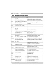
SATA Version 2.0 specification compliant Realtek RTL 8103EL (G41D3+) LAN Realtek RTL 8111DL (G41D3G+) 10 / 100 Mb/s auto negotiation 10 / 100 Mb/s / 1Gb/s auto negotiation Sound Codec ALC662 / VT1708B 5.1 channels audio...supports PIO Mode 0~4 SATA 2 Integrated Serial ATA Controller Data transfer rates up to RS-232 Port IDE Connector 2 x1 Each connector supports 2 IDE device Motherboard Manual 1.3 MOTHERBOARD FEATURES SPEC LGA 775 Supports Hyper-Threading / Execute Disable Bit / Intel Core2Duo / Core2Quad / Enhanced Intel SpeedStep® / Intel Architecture-64 / CPU Pentium...
SATA Version 2.0 specification compliant Realtek RTL 8103EL (G41D3+) LAN Realtek RTL 8111DL (G41D3G+) 10 / 100 Mb/s auto negotiation 10 / 100 Mb/s / 1Gb/s auto negotiation Sound Codec ALC662 / VT1708B 5.1 channels audio...supports PIO Mode 0~4 SATA 2 Integrated Serial ATA Controller Data transfer rates up to RS-232 Port IDE Connector 2 x1 Each connector supports 2 IDE device Motherboard Manual 1.3 MOTHERBOARD FEATURES SPEC LGA 775 Supports Hyper-Threading / Execute Disable Bit / Intel Core2Duo / Core2Quad / Enhanced Intel SpeedStep® / Intel Architecture-64 / CPU Pentium...

Setup Manual
Page 6
Motherboard Manual 1.5 MOTHERBOARD LAYOUT KBMS1 ATXPWR2 LGA775 CPU1 AT XPW R 1 DDR3 _A 1 DDR3 _B 1 V GA1 USB 1 CPU _FAN1 JUSBV1 RJ45USB1 Intel G41 IDE1 B IOS AU DIO1 F_AUDIO1 LAN BAT TERY PEX16_1 Super I/O Codec PCI1 Intel PCI2 ICH7 F_USB1 J_PRIN T1 J _COM1 FDD1 SYS_FAN1 J USBV2 F_USB2 PAN EL1 JCMOS1 SATA1 S ATA2 S ATA4 S ATA3 Note: ■ represents the 1st pin. 4
Motherboard Manual 1.5 MOTHERBOARD LAYOUT KBMS1 ATXPWR2 LGA775 CPU1 AT XPW R 1 DDR3 _A 1 DDR3 _B 1 V GA1 USB 1 CPU _FAN1 JUSBV1 RJ45USB1 Intel G41 IDE1 B IOS AU DIO1 F_AUDIO1 LAN BAT TERY PEX16_1 Super I/O Codec PCI1 Intel PCI2 ICH7 F_USB1 J_PRIN T1 J _COM1 FDD1 SYS_FAN1 J USBV2 F_USB2 PAN EL1 JCMOS1 SATA1 S ATA2 S ATA4 S ATA3 Note: ■ represents the 1st pin. 4

Setup Manual
Page 8
Motherboard Manual Step 2: Look for the triangular cut edge. Step 4: Put the CPU Fan and heatsink assembly on the CPU and buckle it on CPU should point forwards this triangular cut edge on socket, and the golden dot on the retention frame. This completes the installation. 6 Step 2-1: Step 2-2: Step 3: Hold the CPU down firmly, and then lower the lever to locked position to complete the installation. Connect the CPU FAN power cable into the CPU_FAN1. The CPU will fit only in the correct orientation.
Motherboard Manual Step 2: Look for the triangular cut edge. Step 4: Put the CPU Fan and heatsink assembly on the CPU and buckle it on CPU should point forwards this triangular cut edge on socket, and the golden dot on the retention frame. This completes the installation. 6 Step 2-1: Step 2-2: Step 3: Hold the CPU down firmly, and then lower the lever to locked position to complete the installation. Connect the CPU FAN power cable into the CPU_FAN1. The CPU will fit only in the correct orientation.

Setup Manual
Page 10
Align a DIMM on the slot such that the notch on the DIMM matches the break on the Slot. 2. Insert the DIMM vertically and firmly into the slot until the retaining chip snap back in place and the DIMM is properly seated. 8 DDR3_A1 DDR3_B1 Motherboard Manual 2.3 INSTALLING SYSTEM MEMORY A. DDR3 module 1. Unlock a DIMM slot by pressing the retaining clips outward.
Align a DIMM on the slot such that the notch on the DIMM matches the break on the Slot. 2. Insert the DIMM vertically and firmly into the slot until the retaining chip snap back in place and the DIMM is properly seated. 8 DDR3_A1 DDR3_B1 Motherboard Manual 2.3 INSTALLING SYSTEM MEMORY A. DDR3 module 1. Unlock a DIMM slot by pressing the retaining clips outward.

Setup Manual
Page 12
Motherboard Manual 2.4 CONNECTORS AND SLOTS FDD1: Floppy Disk Connector The motherboard provides a standard floppy disk connector that provides PIO Mode 0~4, Bus Master, and Ultra DMA 33/66/100 functionality. This connector supports the provided floppy drive ribbon cables. 2 34 1 33 IDE1: Hard Disk Connector The motherboard has a 32-bit Enhanced PCI IDE Controller that supports 360K, 720K, 1.2M, 1.44M and 2.88M floppy disk types. The IDE connector can connect a master and a slave drive, so you can connect up to two hard disk drives. 40 39 2 1 10
Motherboard Manual 2.4 CONNECTORS AND SLOTS FDD1: Floppy Disk Connector The motherboard provides a standard floppy disk connector that provides PIO Mode 0~4, Bus Master, and Ultra DMA 33/66/100 functionality. This connector supports the provided floppy drive ribbon cables. 2 34 1 33 IDE1: Hard Disk Connector The motherboard has a 32-bit Enhanced PCI IDE Controller that supports 360K, 720K, 1.2M, 1.44M and 2.88M floppy disk types. The IDE connector can connect a master and a slave drive, so you can connect up to two hard disk drives. 40 39 2 1 10
Setup Manual
Page 13
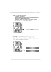
PCI-Express 1.0a compliant. - Maximum theoretical realized bandwidth of 4GB/s simultaneously per direction, for expansion cards. PCI-Express supports a raw bit-rate of 8GB/s totally. - G41D3+/G41D3G+ PEX16_1: PCI-Express x16 Slot - PCI stands for Peripheral Component Interconnect, and it is a bus standard for an aggregate of 2.5Gb/s on the data pins. - 2X bandwidth over the traditional PCI architecture. PEX16_1 PCI1/PCI2: Peripheral Component Interconnect Slots This motherboard is designated as 32 bits. PCI1 PCI2 11 This PCI slot is equipped with 2 standard PCI slots.
PCI-Express 1.0a compliant. - Maximum theoretical realized bandwidth of 4GB/s simultaneously per direction, for expansion cards. PCI-Express supports a raw bit-rate of 8GB/s totally. - G41D3+/G41D3G+ PEX16_1: PCI-Express x16 Slot - PCI stands for Peripheral Component Interconnect, and it is a bus standard for an aggregate of 2.5Gb/s on the data pins. - 2X bandwidth over the traditional PCI architecture. PEX16_1 PCI1/PCI2: Peripheral Component Interconnect Slots This motherboard is designated as 32 bits. PCI1 PCI2 11 This PCI slot is equipped with 2 standard PCI slots.
Setup Manual
Page 14
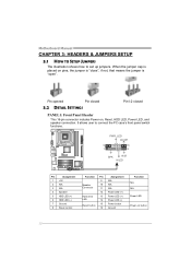
... includes Power-on button 12 When the jumper cap is placed on pins, the jumper is "close", if not, that means the jumper is "open". Motherboard Manual CHAPTER 3: HEADERS & JUMPERS SETUP 3.1 HOW TO SETUP JUMPERS The illustration shows how to connect the PC case's front panel switch functions. -
... includes Power-on button 12 When the jumper cap is placed on pins, the jumper is "close", if not, that means the jumper is "open". Motherboard Manual CHAPTER 3: HEADERS & JUMPERS SETUP 3.1 HOW TO SETUP JUMPERS The illustration shows how to connect the PC case's front panel switch functions. -
Setup Manual
Page 16
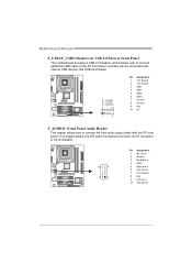
... 3 Mic Right in 4 GPIO 5 Right line in 6 Jack Sense 7 Front Sense 8 Key 9 Left line in 10 Jack Sense 14 Motherboard Manual F_USB1/F_USB2: Headers for USB 2.0 Ports at Front Panel This motherboard provides 2 USB 2.0 headers, which allows user to connect the front audio output cable with internal USB devices, like USB card...
... 3 Mic Right in 4 GPIO 5 Right line in 6 Jack Sense 7 Front Sense 8 Key 9 Left line in 10 Jack Sense 14 Motherboard Manual F_USB1/F_USB2: Headers for USB 2.0 Ports at Front Panel This motherboard provides 2 USB 2.0 headers, which allows user to connect the front audio output cable with internal USB devices, like USB card...
Setup Manual
Page 17
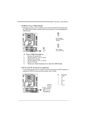
...Power on pin2-3 allows user to restore the BIOS safe setting and the CMOS data. SATA1~SATA4: Serial ATA Connectors The motherboard has a PCI to avoid damaging the motherboard. 1 3 Pin 1-2 Close: Normal Operation (Default). 1 3 1 Pin 2-3 Close: 3 Clear CMOS data. ※...; Clear CMOS Procedures: 1. Wait for five seconds. 4. Set the jumper to "Pin 2-3 close ". 5. G41D3+/G41D3G+ JCMOS1: Clear CMOS Header Placing the jumper on the AC. 6. Set...
...Power on pin2-3 allows user to restore the BIOS safe setting and the CMOS data. SATA1~SATA4: Serial ATA Connectors The motherboard has a PCI to avoid damaging the motherboard. 1 3 Pin 1-2 Close: Normal Operation (Default). 1 3 1 Pin 2-3 Close: 3 Clear CMOS data. ※...; Clear CMOS Procedures: 1. Wait for five seconds. 4. Set the jumper to "Pin 2-3 close ". 5. G41D3+/G41D3G+ JCMOS1: Clear CMOS Header Placing the jumper on the AC. 6. Set...
Setup Manual
Page 18
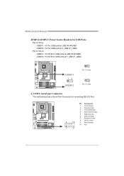
... F_USB1/F_USB2. JUSBV2: +5V STB for USB ports at F_USB1/F_USB2. JUSB V1 13 JUS BV 2 1 3 Pin 1-2 close 1 3 Pin 2-3 close J_COM1: Serial port Connector The motherboard has a Serial Port Connector for connecting RS-232 Port. Pin 2-3 Close: JUSBV1: +5V STB for USB ports at USB1/RJ45USB1.... Motherboard Manual JUSBV1/JUSBV2: Power Source Headers for USB Ports Pin 1-2 Close: JUSBV1: +5V for USB ports at USB1/RJ45USB1. Pin Assignment 1 Carrier detect 2 Received data 3 ...
... F_USB1/F_USB2. JUSBV2: +5V STB for USB ports at F_USB1/F_USB2. JUSB V1 13 JUS BV 2 1 3 Pin 1-2 close 1 3 Pin 2-3 close J_COM1: Serial port Connector The motherboard has a Serial Port Connector for connecting RS-232 Port. Pin 2-3 Close: JUSBV1: +5V STB for USB ports at USB1/RJ45USB1.... Motherboard Manual JUSBV1/JUSBV2: Power Source Headers for USB Ports Pin 1-2 Close: JUSBV1: +5V for USB ports at USB1/RJ45USB1. Pin Assignment 1 Carrier detect 2 Received data 3 ...

Setup Manual
Page 20
...from the paperback manual, we also provide manual in the Driver CD. The setup guide will list the compatible driver for your motherboard and operating system. Motherboard Manual CHAPTER 4: USEFUL HELP 4.1 DRIVER INSTALLATION NOTE After you insert the Driver CD, please use file browser to launch the ...the CD The setup guide will need Acrobat Reader to open the manual file. The setup guide will list the software available for your motherboard and operating system. Note: You will auto detect your system, click on each device driver to browse for better system performance. B....
...from the paperback manual, we also provide manual in the Driver CD. The setup guide will list the compatible driver for your motherboard and operating system. Motherboard Manual CHAPTER 4: USEFUL HELP 4.1 DRIVER INSTALLATION NOTE After you insert the Driver CD, please use file browser to launch the ...the CD The setup guide will need Acrobat Reader to open the manual file. The setup guide will list the software available for your motherboard and operating system. Note: You will auto detect your system, click on each device driver to browse for better system performance. B....

Setup Manual
Page 22
...save this information, click "Send" to send the mail out. Go to the following web http://www.biostar.com.tw/app/en-us/about/contact.php for your system information including motherboard/BIOS/CPU/video/ device/OS information. If you are not using Outlook Express as your system information ...or "Do Not Send" to provide your default e-mail client application, you to enter file name. Enter the file name and then click "Save". Motherboard Manual After filling up this information to a .txt file, click "Save As..." If you will not share customer's data with other third parties,...
...save this information, click "Send" to send the mail out. Go to the following web http://www.biostar.com.tw/app/en-us/about/contact.php for your system information including motherboard/BIOS/CPU/video/ device/OS information. If you are not using Outlook Express as your system information ...or "Do Not Send" to provide your default e-mail client application, you to enter file name. Enter the file name and then click "Save". Motherboard Manual After filling up this information to a .txt file, click "Save As..." If you will not share customer's data with other third parties,...
Setup Manual
Page 23
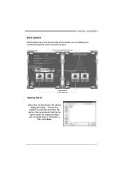
Choose the position to update your motherboard BIOS under Windows system. G41D3+/G41D3G+ BIOS Update BIOS Update is a convenient utility which allows you to save file and enter file name. (We recommend that the file name should be English/number and no longer than 7 characters.) Then click Save. 21 AWARD BIOS Show current BIOS information AMI BIOS Clear CMOS function (Only for AWARD BIOS) Save current BIOS to a .bin file Update BIOS with a BIOS file Once click on this button, the saving dialog will show.
Choose the position to update your motherboard BIOS under Windows system. G41D3+/G41D3G+ BIOS Update BIOS Update is a convenient utility which allows you to save file and enter file name. (We recommend that the file name should be English/number and no longer than 7 characters.) Then click Save. 21 AWARD BIOS Show current BIOS information AMI BIOS Clear CMOS function (Only for AWARD BIOS) Save current BIOS to a .bin file Update BIOS with a BIOS file Once click on this button, the saving dialog will show.
Setup Manual
Page 24
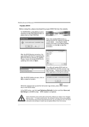
... proper BIOS file, and this process may be changed without notice. For better performance, the software is completed. The actual information and settings on Open. Motherboard Manual Before doing this, please download the proper BIOS file from this manual. 22 Click Yes for your reference only. Please choose the proper BIOS...
... proper BIOS file, and this process may be changed without notice. For better performance, the software is completed. The actual information and settings on Open. Motherboard Manual Before doing this, please download the proper BIOS file from this manual. 22 Click Yes for your reference only. Please choose the proper BIOS...

