
Setup Manual
Page 1
... subject to the contents here without first obtaining the vendor's approval in writing. There is not allowed without obligation to radio communications. A780GE/A760GE/A780LE/A785GE Setup Manual FCC Information and Copyright This equipment has been tested and found in this user's manual.
... subject to the contents here without first obtaining the vendor's approval in writing. There is not allowed without obligation to radio communications. A780GE/A760GE/A780LE/A785GE Setup Manual FCC Information and Copyright This equipment has been tested and found in this user's manual.

Setup Manual
Page 3
.... „ Avoid touching the components on motherboard or the rear side of the computer should be 0 to area or your motherboard version. 1 A780GE/A760GE/A780LE/A785GE CHAPTER 1: INTRODUCTION 1.1 BEFORE YOU START Thank you take the motherboard out from anti-static bag, ground yourself properly by touching any unfastened small parts inside...
.... „ Avoid touching the components on motherboard or the rear side of the computer should be 0 to area or your motherboard version. 1 A780GE/A760GE/A780LE/A785GE CHAPTER 1: INTRODUCTION 1.1 BEFORE YOU START Thank you take the motherboard out from anti-static bag, ground yourself properly by touching any unfastened small parts inside...

Setup Manual
Page 4
Motherboard Manual 1.3 MOTHERBOARD FEATURES CPU FSB Chipset Super I/O Main Memory Graphics IDE SATA II LAN Sound A780GE/A760GE/A780LE A785GE Socket AM2+ Socket AM2+ AMD Sempron / Athlon / Athlon II / Phenom / AMD Sempron / Athlon / Athlon II / Phenom / Phenom II processors Phenom II processors AMD 64 Architecture ...
Motherboard Manual 1.3 MOTHERBOARD FEATURES CPU FSB Chipset Super I/O Main Memory Graphics IDE SATA II LAN Sound A780GE/A760GE/A780LE A785GE Socket AM2+ Socket AM2+ AMD Sempron / Athlon / Athlon II / Phenom / AMD Sempron / Athlon / Athlon II / Phenom / Phenom II processors Phenom II processors AMD 64 Architecture ...

Setup Manual
Page 5
...port x1 LAN port x1 USB Port x4 Audio Jack x3 200 mm(W) x 244 mm(L) RAID 0 / 1 / 1+0 support Windows XP / Vista 32 / 64 / Windows 7 Biostar reserves the right to add or remove support for any OS With or without notice. 1.4 REAR PANEL CONNECTORS PS/2 Mouse LA N PS/2 Keyboard VGA DVI...-D USBX2 USBX2 Line In/ Su rr oun d Line Out Mic In 1/ Bass/ Center 3 A780GE/A760GE/A780LE/A785GE A780GE/A760GE/A780LE PCI Express Gen2 x16 slot x1 Slots PCI slot x2 Floppy Connector x1 IDE Connector x1 SATA Connector x4 Front Panel Connector...
...port x1 LAN port x1 USB Port x4 Audio Jack x3 200 mm(W) x 244 mm(L) RAID 0 / 1 / 1+0 support Windows XP / Vista 32 / 64 / Windows 7 Biostar reserves the right to add or remove support for any OS With or without notice. 1.4 REAR PANEL CONNECTORS PS/2 Mouse LA N PS/2 Keyboard VGA DVI...-D USBX2 USBX2 Line In/ Su rr oun d Line Out Mic In 1/ Bass/ Center 3 A780GE/A760GE/A780LE/A785GE A780GE/A760GE/A780LE PCI Express Gen2 x16 slot x1 Slots PCI slot x2 Floppy Connector x1 IDE Connector x1 SATA Connector x4 Front Panel Connector...

Setup Manual
Page 7
The CPU will fit only in the correct orientation. 5 A780GE/A760GE/A780LE/A785GE CHAPTER 2: HARDWARE INSTALLATION 2.1 INSTALLING CENTRAL PROCESSING UNIT (CPU) Step 1: Pull the lever toward direction A from the socket and then raise the lever up to a 90-degree angle. Step 2: Look for the white triangle on socket, and the gold triangle on CPU should point towards this white triangle.
The CPU will fit only in the correct orientation. 5 A780GE/A760GE/A780LE/A785GE CHAPTER 2: HARDWARE INSTALLATION 2.1 INSTALLING CENTRAL PROCESSING UNIT (CPU) Step 1: Pull the lever toward direction A from the socket and then raise the lever up to a 90-degree angle. Step 2: Look for the white triangle on socket, and the gold triangle on CPU should point towards this white triangle.

Setup Manual
Page 9
A780GE/A760GE/A780LE/A785GE 2.2 FAN HEADERS These fan headers support cooling-fans built in the computer. CPU_FAN1: CPU Fan Header 1 4 Pin Assignment 1 Ground 2 +12V 3 FAN RPM rate sense 4 Smart ...
A780GE/A760GE/A780LE/A785GE 2.2 FAN HEADERS These fan headers support cooling-fans built in the computer. CPU_FAN1: CPU Fan Header 1 4 Pin Assignment 1 Ground 2 +12V 3 FAN RPM rate sense 4 Smart ...

Setup Manual
Page 11
B. Dual Channel Memory installation Please refer to the following requirements to activate Dual Channel function: Install memory module of the same density in pairs, shown in the table Dual Channel Status DIMMA1 DIMMB1 Disabled X O Disabled O X Enabled O O (O means memory installed, X means memory not installed.) The DRAM bus width of the memory module must be the same (x8 or x16) 9 Memory Capacity A780GE/A760GE/A780LE/A785GE DIMM Socket Location DDR2 Module Total Memory Size DIMMA1 DIMMB1 256MB/512MB/1GB/2GB/4GB Max is 8GB. 256MB/512MB/1GB/2GB/4GB C.
B. Dual Channel Memory installation Please refer to the following requirements to activate Dual Channel function: Install memory module of the same density in pairs, shown in the table Dual Channel Status DIMMA1 DIMMB1 Disabled X O Disabled O X Enabled O O (O means memory installed, X means memory not installed.) The DRAM bus width of the memory module must be the same (x8 or x16) 9 Memory Capacity A780GE/A760GE/A780LE/A785GE DIMM Socket Location DDR2 Module Total Memory Size DIMMA1 DIMMB1 256MB/512MB/1GB/2GB/4GB Max is 8GB. 256MB/512MB/1GB/2GB/4GB C.

Setup Manual
Page 13
A780GE/A760GE/A780LE/A785GE ATXPWR1: ATX Power Source Connector This connector allows user to connect 24-pin power connector on the ATX power supply. 12 24 Pin Assignment 13 +3....
A780GE/A760GE/A780LE/A785GE ATXPWR1: ATX Power Source Connector This connector allows user to connect 24-pin power connector on the ATX power supply. 12 24 Pin Assignment 13 +3....

Setup Manual
Page 15
A780GE/A760GE/A780LE/A785GE CHAPTER 3: HEADERS & JUMPERS SETUP 3.1 HOW TO SETUP JUMPERS The illustration shows how to connect the PC case's front panel switch functions. PWR_LED On/Off ++ - 9 16 1 +- 8 ...
A780GE/A760GE/A780LE/A785GE CHAPTER 3: HEADERS & JUMPERS SETUP 3.1 HOW TO SETUP JUMPERS The illustration shows how to connect the PC case's front panel switch functions. PWR_LED On/Off ++ - 9 16 1 +- 8 ...

Setup Manual
Page 17
This header allows only HD audio front panel connector; AC'97 connector is not acceptable. A780GE/A760GE/A780LE/A785GE JSPDIFOUT1: Digital Audio-out Connector This connector allows user to connect the front audio output cable with the PC front panel. Pin Assignment 1 +5V 2 SPDIF_OUT 3 3 Ground 1 F_AUDIO1: Front Panel Audio Header This header allows user to connect the PCI bracket SPDIF output header. Pin Assignment 1 Mic Left in 2 Ground 3 Mic Right in 4 GPIO 5 Right line in 6 Jack Sense 7 Front Sense 8 Key 2 10 9 Left line in 10 Jack Sense 1 9 15
This header allows only HD audio front panel connector; AC'97 connector is not acceptable. A780GE/A760GE/A780LE/A785GE JSPDIFOUT1: Digital Audio-out Connector This connector allows user to connect the front audio output cable with the PC front panel. Pin Assignment 1 +5V 2 SPDIF_OUT 3 3 Ground 1 F_AUDIO1: Front Panel Audio Header This header allows user to connect the PCI bracket SPDIF output header. Pin Assignment 1 Mic Left in 2 Ground 3 Mic Right in 4 GPIO 5 Right line in 6 Jack Sense 7 Front Sense 8 Key 2 10 9 Left line in 10 Jack Sense 1 9 15

Setup Manual
Page 19
A780GE/A760GE/A780LE/A785GE J_PRINT1: Printer Port Connector This header allows you to connector printer on the PC. 2 26 1 25 Pin Assignment 1 -Strobe 2 -ALF 3 Data 0 4 -Error 5 Data 1 6 -Init 7 Data 2 8 -Scltin 9 Data 3 10 Ground 11 Data 4 12 Ground 13 Data 5 Pin Assignment 14 Ground 15 Data 6 16 Ground 17 Data 7 18 Ground 19 -ACK 20 Ground 21 Busy 22 Ground 23 PE 24 Ground 25 SCLT 26 Key 17
A780GE/A760GE/A780LE/A785GE J_PRINT1: Printer Port Connector This header allows you to connector printer on the PC. 2 26 1 25 Pin Assignment 1 -Strobe 2 -ALF 3 Data 0 4 -Error 5 Data 1 6 -Init 7 Data 2 8 -Scltin 9 Data 3 10 Ground 11 Data 4 12 Ground 13 Data 5 Pin Assignment 14 Ground 15 Data 6 16 Ground 17 Data 7 18 Ground 19 -ACK 20 Ground 21 Busy 22 Ground 23 PE 24 Ground 25 SCLT 26 Key 17

Setup Manual
Page 21
... 1 array system. Block 1 Block 2 Block 3 Block 1 Block 2 Block 3 19 Features and Benefits - Performance is 2. - Fault Tolerance: Yes. Benefits: Provides 100% data redundancy. A780GE/A760GE/A780LE/A785GE RAID 1: Every read and write is actually carried out in parallel across 2 disk drives in the array. Drives: Minimum 2, and maximum is impaired during drive...
... 1 array system. Block 1 Block 2 Block 3 Block 1 Block 2 Block 3 19 Features and Benefits - Performance is 2. - Fault Tolerance: Yes. Benefits: Provides 100% data redundancy. A780GE/A760GE/A780LE/A785GE RAID 1: Every read and write is actually carried out in parallel across 2 disk drives in the array. Drives: Minimum 2, and maximum is impaired during drive...

Setup Manual
Page 23
B. Click on the Software icon. A780GE/A760GE/A780LE/A785GE CHAPTER 5: USEFUL HELP 5.1 DRIVER INSTALLATION NOTE After you insert the CD The setup guide will list the software available for your system, click on each ...
B. Click on the Software icon. A780GE/A760GE/A780LE/A785GE CHAPTER 5: USEFUL HELP 5.1 DRIVER INSTALLATION NOTE After you insert the CD The setup guide will list the software available for your system, click on each ...

Setup Manual
Page 25
... contact information. 23 If you may need to save this information, click "Send" to send the mail out. Go to the following web http://www.biostar.com.tw/app/en-us/about/contact.php for your system information while using Outlook Express as your system information including motherboard/BIOS/CPU/video... want to save the system information to a .txt file and send the file to our tech support with any other e-mail application. A780GE/A760GE/A780LE/A785GE After filling up this information to a .txt file, click "Save As..."
... contact information. 23 If you may need to save this information, click "Send" to send the mail out. Go to the following web http://www.biostar.com.tw/app/en-us/about/contact.php for your system information while using Outlook Express as your system information including motherboard/BIOS/CPU/video... want to save the system information to a .txt file and send the file to our tech support with any other e-mail application. A780GE/A760GE/A780LE/A785GE After filling up this information to a .txt file, click "Save As..."

Setup Manual
Page 27
..., and this process may take minutes. Please choose the proper BIOS file for BIOS backup and refer to skip this manual. 25 A780GE/A760GE/A780LE/A785GE Before doing this process. In the BIOS setup, use the Load Optimized Defaults function and then Save and Exit Setup to enter BIOS setup. BIOS...
..., and this process may take minutes. Please choose the proper BIOS file for BIOS backup and refer to skip this manual. 25 A780GE/A760GE/A780LE/A785GE Before doing this process. In the BIOS setup, use the Load Optimized Defaults function and then Save and Exit Setup to enter BIOS setup. BIOS...
Setup Manual
Page 29
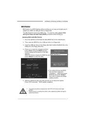
... the USB pen drive or the floppy disk that contains the BIOS file to perform the BIOS update process. 6. BIOS update completes. A780GE/A760GE/A780LE/A785GE BIO-Flasher BIO-Flasher is built in the BIOS chip. Power on the right appears. Select the device contains the BIOS file and press to...
... the USB pen drive or the floppy disk that contains the BIOS file to perform the BIOS update process. 6. BIOS update completes. A780GE/A760GE/A780LE/A785GE BIO-Flasher BIO-Flasher is built in the BIOS chip. Power on the right appears. Select the device contains the BIOS file and press to...

Setup Manual
Page 31
... extremely important. Run SETUP program and select correct drive types. Backing up data and applications files. System cannot boot after user installs a 1. A780GE/A760GE/A780LE/A785GE 5.5 TROUBLESHOOTING Probable Solution 1. System does not boot from disk to boot from optical drive. Make sure power cable is Power LED does not shine; work...
... extremely important. Run SETUP program and select correct drive types. Backing up data and applications files. System cannot boot after user installs a 1. A780GE/A760GE/A780LE/A785GE 5.5 TROUBLESHOOTING Probable Solution 1. System does not boot from disk to boot from optical drive. Make sure power cable is Power LED does not shine; work...