Installation Manual
Page 1
INSTALLATION MANUAL P-105 AM/FM/MPX RADIO WITH COMPACT DISC PLAYER, CD CHANGER CONTROLS AND QUARTZ CLOCK
INSTALLATION MANUAL P-105 AM/FM/MPX RADIO WITH COMPACT DISC PLAYER, CD CHANGER CONTROLS AND QUARTZ CLOCK

Installation Manual
Page 2
... mount the radio to the sub-dash. In this is not the case, it available, call our toll-free "HELP" line at electronics supply stores and car stereo specialty shops. Remove all radios have removable mounting brackets. color code relationship expressed in conjunction with a 1-1/2 DIN radio opening. b. NOTE: The Dimmer function may need to be connected to your P-105 even before purchasing to car antenna lead, if needed . INSTALLATION INSTRUCTIONS This unit is designed for the radio chassis. a. Install Wiring...
... mount the radio to the sub-dash. In this is not the case, it available, call our toll-free "HELP" line at electronics supply stores and car stereo specialty shops. Remove all radios have removable mounting brackets. color code relationship expressed in conjunction with a 1-1/2 DIN radio opening. b. NOTE: The Dimmer function may need to be connected to your P-105 even before purchasing to car antenna lead, if needed . INSTALLATION INSTRUCTIONS This unit is designed for the radio chassis. a. Install Wiring...
Installation Manual
Page 3
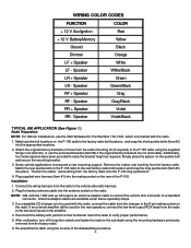
... external amplifier will require an antenna adapter cable to convert the vehicle mini connector to raise the bracket height as required. Reconnect the battery and perform a brief functional test of the P-105. Speaker Gray/Black RR + Speaker Violet RR - Some vehicle applications incorporate a rear mounting support. Connect the wiring harness from the radio to the rear factory radio bolt location and snap the long quickie bolt (Item #3) into the appropriate locations. 2. WIRING COLOR CODES FUNCTION COLOR + 12...
... external amplifier will require an antenna adapter cable to convert the vehicle mini connector to raise the bracket height as required. Reconnect the battery and perform a brief functional test of the P-105. Speaker Gray/Black RR + Speaker Violet RR - Some vehicle applications incorporate a rear mounting support. Connect the wiring harness from the radio to the rear factory radio bolt location and snap the long quickie bolt (Item #3) into the appropriate locations. 2. WIRING COLOR CODES FUNCTION COLOR + 12...
Installation Manual
Page 4
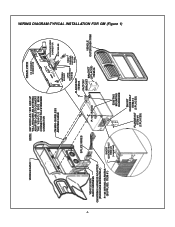
... #4 REAR BUSHING FACTORY RADIO FACTORY BRACKET BRACKET (2 PLACES) ITEM #6 VEHICLE OUTER DASH TRIM SHORT QUICKIE BOLT ITEM #2 (supplied) EXISTING MOUNTING HARDWARE SHORT QUICKIE BOLT ITEM # 2 FLANGENUT (2 PLACES) ITEM #4 (2 PLACES) WIRING DIAGRAM-TYPICAL INSTALLATION FOR GM (Figure 1) -4- VEHICLE DASH NOTE: GM VEHICLES 1992 AND UP WILL REQUIRE AN ANTENNA ADAPTER CABLE TO CONVERT THE VEHICLE SIDE MINI CONNECTOR TO A STANDARD CONNECTOR REAR VIEW CD CHANGER CONNECTOR VEHICLE SIDE RADIO HARNESS GM WIRING HARNESS ADAPTER (PURCHASE SEPARATELY) P-105 WIRING HARNESS...
... #4 REAR BUSHING FACTORY RADIO FACTORY BRACKET BRACKET (2 PLACES) ITEM #6 VEHICLE OUTER DASH TRIM SHORT QUICKIE BOLT ITEM #2 (supplied) EXISTING MOUNTING HARDWARE SHORT QUICKIE BOLT ITEM # 2 FLANGENUT (2 PLACES) ITEM #4 (2 PLACES) WIRING DIAGRAM-TYPICAL INSTALLATION FOR GM (Figure 1) -4- VEHICLE DASH NOTE: GM VEHICLES 1992 AND UP WILL REQUIRE AN ANTENNA ADAPTER CABLE TO CONVERT THE VEHICLE SIDE MINI CONNECTOR TO A STANDARD CONNECTOR REAR VIEW CD CHANGER CONNECTOR VEHICLE SIDE RADIO HARNESS GM WIRING HARNESS ADAPTER (PURCHASE SEPARATELY) P-105 WIRING HARNESS...
Installation Manual
Page 5
... the radio side harness along with this radio, connect the cable from the harness to the radio antenna connector. 4. Connect the vehicle antenna cable to the radio. 4. Re-assemble the dash using the short quickie bolt (Item #2) and the flange nut (Item # 4) provided. 2. Installation: 1. If an external amplifier will be used for the rear speakers, connect the low-level output RCA leads from the radio to the vehicle side wiring harness. 3. Attach the mounting tabs to the 8-pin...
... the radio side harness along with this radio, connect the cable from the harness to the radio antenna connector. 4. Connect the vehicle antenna cable to the radio. 4. Re-assemble the dash using the short quickie bolt (Item #2) and the flange nut (Item # 4) provided. 2. Installation: 1. If an external amplifier will be used for the rear speakers, connect the low-level output RCA leads from the radio to the vehicle side wiring harness. 3. Attach the mounting tabs to the 8-pin...
Installation Manual
Page 6
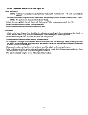
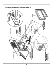
TYPICAL INSTALLATION FOR CHRYSLER (Figure 2) -6- VEHICLE DASH VEHICLE SIDE RADIO HARNESS CHRYSLER WIRING HARNESS ADAPTER (PURCHASED SEPARATELY) P-105 WIRING HARNESS ANTENNA CABLE REAR VIEW CD CHANGER CONNECTOR FLANGE NUT ITEM #4 (supplied) VEHICLE SIDE GROUNDING STRAP ANTENNA SOCKET 14 PIN PWR/SPKR CONNECTOR RCA CABLES LONG QUICKIE BOLT ITEM #3 SPLICE WIRES P-105 RADIO VEHICLE OUTER DASH TRIM CHRYSLER APPLICATION MOUNTING TABS AND HARDWARE (See Figures 3, 4 and 5) EXISTING MOUNTING HARDWARE OR 10mm SCREWS
TYPICAL INSTALLATION FOR CHRYSLER (Figure 2) -6- VEHICLE DASH VEHICLE SIDE RADIO HARNESS CHRYSLER WIRING HARNESS ADAPTER (PURCHASED SEPARATELY) P-105 WIRING HARNESS ANTENNA CABLE REAR VIEW CD CHANGER CONNECTOR FLANGE NUT ITEM #4 (supplied) VEHICLE SIDE GROUNDING STRAP ANTENNA SOCKET 14 PIN PWR/SPKR CONNECTOR RCA CABLES LONG QUICKIE BOLT ITEM #3 SPLICE WIRES P-105 RADIO VEHICLE OUTER DASH TRIM CHRYSLER APPLICATION MOUNTING TABS AND HARDWARE (See Figures 3, 4 and 5) EXISTING MOUNTING HARDWARE OR 10mm SCREWS

Installation Manual
Page 8
© 2001 Audiovox Electronics Corp., Hauppauge, NY 11788 128-5914A
© 2001 Audiovox Electronics Corp., Hauppauge, NY 11788 128-5914A


