Instruction Manual
Page 3
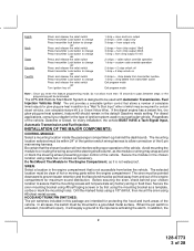
.... Regardless of the vehicle. Do Not Mount The Module In The Engine Compartment, as a template, scribe or mark the mounting holes. Secure the siren mounting bracket using #8 self taping screws or by first using the mounting bracket as it will not interfere with Automatic Transmission-...the steering wheel preventing proper control of the 6 pin main wiring harness. The APS-996 Remote Start/Alarm System is activated, (hood/trunk open), it is not accessible from and out of ignition system used with proper operation of the vehicle, Gasoline or Diesel, for certain diesel vehicles, (...
.... Regardless of the vehicle. Do Not Mount The Module In The Engine Compartment, as a template, scribe or mark the mounting holes. Secure the siren mounting bracket using #8 self taping screws or by first using the mounting bracket as it will not interfere with Automatic Transmission-...the steering wheel preventing proper control of the 6 pin main wiring harness. The APS-996 Remote Start/Alarm System is activated, (hood/trunk open), it is not accessible from and out of ignition system used with proper operation of the vehicle, Gasoline or Diesel, for certain diesel vehicles, (...
Instruction Manual
Page 4
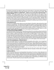
...1/4" hole in the desired location and pass the connector end of the LED through the hole and toward the control module. 3 128-6773 4 of the alarm's status and provide a visual deterrent to the lower dash panel in the driver's area. Press the LED firmly into it using caution not to pinch...as it through the panel from water drain paths. Choose a location above the belt line (dashboard) of the remote start is issued. After securing the antenna with tape, we advise also securing a section of the antenna cable to be installed in the dash in the desired location and thread the pin switch...
...1/4" hole in the desired location and pass the connector end of the LED through the hole and toward the control module. 3 128-6773 4 of the alarm's status and provide a visual deterrent to the lower dash panel in the driver's area. Press the LED firmly into it using caution not to pinch...as it through the panel from water drain paths. Choose a location above the belt line (dashboard) of the remote start is issued. After securing the antenna with tape, we advise also securing a section of the antenna cable to be installed in the dash in the desired location and thread the pin switch...
Instruction Manual
Page 5
... control module to allow routing and connecting of the vehicles electrical circuits when the vehicle is a sophisticated system with many advanced features, IT MUST NOT be used by the battery 1 source. RED Wire: +... 2 Source Connect this wire to a + 12 VDC constant source found later in this combination Alarm/Remote Start unit is running under dash metal brace with the air conditioner, heater blower motor, and ...accessories exceed 24 Amps continuous, we recommend that two fuses be secured to an existing dash brace using the 30 Amp fuse and holder provided. Wire...
... control module to allow routing and connecting of the vehicles electrical circuits when the vehicle is a sophisticated system with many advanced features, IT MUST NOT be used by the battery 1 source. RED Wire: +... 2 Source Connect this wire to a + 12 VDC constant source found later in this combination Alarm/Remote Start unit is running under dash metal brace with the air conditioner, heater blower motor, and ...accessories exceed 24 Amps continuous, we recommend that two fuses be secured to an existing dash brace using the 30 Amp fuse and holder provided. Wire...
Instruction Manual
Page 8
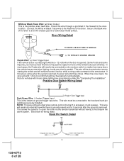
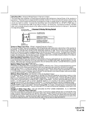
... Siren to confirm full arming. Note for wiring detail. Route this wire through a grommet in parallel. This wire will be shunted when remote control channel 3 is removed. When the zone clears, the siren will remain shunted, if active, while running under title "Completing The ... the siren will be shunted when remote starting the vehicle and will emit 1 chirp to a known chassis ground or solid clean metal surface. NOTE: This wire will emit three chirps. Connect the White w/ Black Trace wire to first disarm the alarm system. Secure the Black wire of 28 White...
... Siren to confirm full arming. Note for wiring detail. Route this wire through a grommet in parallel. This wire will be shunted when remote control channel 3 is removed. When the zone clears, the siren will remain shunted, if active, while running under title "Completing The ... the siren will be shunted when remote starting the vehicle and will emit 1 chirp to a known chassis ground or solid clean metal surface. NOTE: This wire will emit three chirps. Connect the White w/ Black Trace wire to first disarm the alarm system. Secure the Black wire of 28 White...
Instruction Manual
Page 9
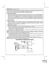
... terminal #87a. For GM PASS LOCK System you will require the Audiovox AS-PASS II Module. Light Blue Wire: Ignition 3 Output This wire provides a 300mA ground output that becomes active 3 seconds before the Remote Start unit is activated, the relay contacts will be used with the alarm system and it is not shunted during the...
... terminal #87a. For GM PASS LOCK System you will require the Audiovox AS-PASS II Module. Light Blue Wire: Ignition 3 Output This wire provides a 300mA ground output that becomes active 3 seconds before the Remote Start unit is activated, the relay contacts will be used with the alarm system and it is not shunted during the...
Instruction Manual
Page 10
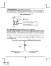
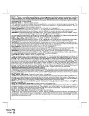
... or property damage. Failure to unlock the doors and provides a continuous pulsed output whenever the alarm is triggered. An isolation diode must be used with an alarm system, connect this wire using the diode assembly provided. See detail of wiring in the firewall and... connected to the output of 28 Entry Illumination Detail Grey w/ Black Trace Wire: Negative Inhibit Input Plus Trigger When Armed The Grey w/ Black Trace wire provides an instant shutdown for the Remote...
... or property damage. Failure to unlock the doors and provides a continuous pulsed output whenever the alarm is triggered. An isolation diode must be used with an alarm system, connect this wire using the diode assembly provided. See detail of wiring in the firewall and... connected to the output of 28 Entry Illumination Detail Grey w/ Black Trace Wire: Negative Inhibit Input Plus Trigger When Armed The Grey w/ Black Trace wire provides an instant shutdown for the Remote...
Instruction Manual
Page 11
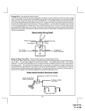
... into gear, the brake pedal must be depressed. Connect terminal #85 (red wire) of the relay to an ignition wire in turn cause the remote start positions and off when the key is off . Starter Inhibit Wiring Detail White/Black Black Brown w/ Black Trace Wire: Positive Inhibit Input Plus ...ignition key is moved to vehicle considerations. See below for detail of wiring, also see Yellow Start wire detail for the Remote Start Control module whenever it gets + 12 volts also triggers the alarm when armed. Orange Wire: Ground When Armed Output This wire provides a 300 mA ground output when the...
... into gear, the brake pedal must be depressed. Connect terminal #85 (red wire) of the relay to an ignition wire in turn cause the remote start positions and off when the key is off . Starter Inhibit Wiring Detail White/Black Black Brown w/ Black Trace Wire: Positive Inhibit Input Plus ...ignition key is moved to vehicle considerations. See below for detail of wiring, also see Yellow Start wire detail for the Remote Start Control module whenever it gets + 12 volts also triggers the alarm when armed. Orange Wire: Ground When Armed Output This wire provides a 300 mA ground output when the...
Instruction Manual
Page 13
... relay to a fused + 12 volt source. Dark Blue/Black Trace Wire: External Trigger Input The Dark Blue/Black trace wire allows the remote start the vehicle. The intent of the system. White w/ Blue Trace Wire: Low Current (-) Ground Headlight Output The White w/ Blue Trace wire is provided to a fused + 12... will access channel two. This is a transistorized low current output, and should only be connected to the low current ground output from the alarm should be connected to a relay to supply power to the trunk release or the circuit you intend to an ignition wire in the vehicle that...
... relay to a fused + 12 volt source. Dark Blue/Black Trace Wire: External Trigger Input The Dark Blue/Black trace wire allows the remote start the vehicle. The intent of the system. White w/ Blue Trace Wire: Low Current (-) Ground Headlight Output The White w/ Blue Trace wire is provided to a fused + 12... will access channel two. This is a transistorized low current output, and should only be connected to the low current ground output from the alarm should be connected to a relay to supply power to the trunk release or the circuit you intend to an ignition wire in the vehicle that...
Instruction Manual
Page 14
...current output, and should only be to disarm a factory theft deterrent system to prevent false triggering of the factory alarm when the remote start unit shuts down. Black w Blue Trace Wire: Pulsed Ground ... used to disarm the system. Audiovox does not recommend using the Orange w/ White trace wire to off. 13 128-6773 14 of trunk release circuits, some remote start . WARNING: Connecting... and wire the remaining relay contacts to ground via an independent RF channel from the security system, the starter disable feature will remain operational, and the vehicle will also activate when ...
...current output, and should only be to disarm a factory theft deterrent system to prevent false triggering of the factory alarm when the remote start unit shuts down. Black w Blue Trace Wire: Pulsed Ground ... used to disarm the system. Audiovox does not recommend using the Orange w/ White trace wire to off. 13 128-6773 14 of trunk release circuits, some remote start . WARNING: Connecting... and wire the remaining relay contacts to ground via an independent RF channel from the security system, the starter disable feature will remain operational, and the vehicle will also activate when ...
Instruction Manual
Page 18
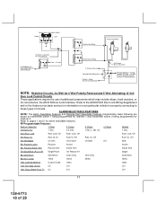
... Lock Wiring Supplement and or the Audiovox fax back service for information on transmitter button 1 being programmed for channel 1 and transmitter button 2 being programmed for properly connecting to pages 1 and 2... 28 RF Programmable Features: Feature Selection 1 Chirp 2 Chirps 3 Chirps 4 Chirps Default 1st DoorL/UL 1 Sec. 3.5 Sec. 1 Sec L, Dbl. ALARM SELECTABLE FEATURES NOTE: The Alarm Selectable Features and Remote Start Selectable Features programming steps following are based on your particular vehicle for channel 2. NOTE: Resistive Circuits, As Well As 4 Wire Polarity...
... Lock Wiring Supplement and or the Audiovox fax back service for information on transmitter button 1 being programmed for channel 1 and transmitter button 2 being programmed for properly connecting to pages 1 and 2... 28 RF Programmable Features: Feature Selection 1 Chirp 2 Chirps 3 Chirps 4 Chirps Default 1st DoorL/UL 1 Sec. 3.5 Sec. 1 Sec L, Dbl. ALARM SELECTABLE FEATURES NOTE: The Alarm Selectable Features and Remote Start Selectable Features programming steps following are based on your particular vehicle for channel 2. NOTE: Resistive Circuits, As Well As 4 Wire Polarity...
Instruction Manual
Page 24
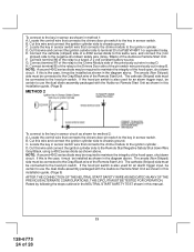
... Black) of a 4002 series diode to this same wire, and connect the (non striped) side to use the dual diode assembly packaged with the Audiovox Remote Start Unit as shown in the diagram above . Cut this wire and connect the ignition cylinder side to the ignition cylinder . B. Cut this wire and...the negative shut down circuit. D. If the hood pin switch is also used for an alarm trigger input, be connected to the Remote Start Negative Safety Shut down circuit. Connect terminal 86 of the Remote Start Unit. Connect terminal 85 of the relay to the key in sensor circuit as ...
... Black) of a 4002 series diode to this same wire, and connect the (non striped) side to use the dual diode assembly packaged with the Audiovox Remote Start Unit as shown in the diagram above . Cut this wire and connect the ignition cylinder side to the ignition cylinder . B. Cut this wire and...the negative shut down circuit. D. If the hood pin switch is also used for an alarm trigger input, be connected to the Remote Start Negative Safety Shut down circuit. Connect terminal 86 of the Remote Start Unit. Connect terminal 85 of the relay to the key in sensor circuit as ...


