Instruction Manual
Page 1
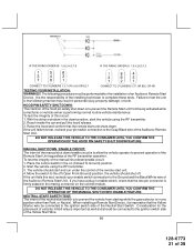
... custom code. lock, dbl 1 sec. Be certain to change or Press and release the valet switch Press transmitter Lock button to place a check mark indicating the method used in the box located on the last page of 28 RF Programmable Features : Feature Selection 1 Chirp 2 Chirps 3 Chirps 4 Chirps Default 1st DoorL/UL 1 Sec. 3.5 Sec. 1 Sec L, Dbl. RY Model APS 996a Installation Manual SELECTABLE...
... custom code. lock, dbl 1 sec. Be certain to change or Press and release the valet switch Press transmitter Lock button to place a check mark indicating the method used in the box located on the last page of 28 RF Programmable Features : Feature Selection 1 Chirp 2 Chirps 3 Chirps 4 Chirps Default 1st DoorL/UL 1 Sec. 3.5 Sec. 1 Sec L, Dbl. RY Model APS 996a Installation Manual SELECTABLE...
Instruction Manual
Page 3
... every installation, the vehicle MUST HAVE a Tach Signal Input, Automatic Transmission and Fuel Injection. The unit provides a selectable ignition control that the mounting screws will be within 24" of the vehicle. Eighth Ninth Tenth Eleventh Twelfth Press and release the valet switch Press transmitter Lock button to change Press transmitter lock button to change or Press and release the valet switch Press transmitter Lock button to change Press transmitter Lock button to change or...
... every installation, the vehicle MUST HAVE a Tach Signal Input, Automatic Transmission and Fuel Injection. The unit provides a selectable ignition control that the mounting screws will be within 24" of the vehicle. Eighth Ninth Tenth Eleventh Twelfth Press and release the valet switch Press transmitter Lock button to change Press transmitter lock button to change or Press and release the valet switch Press transmitter Lock button to change Press transmitter Lock button to change or...
Instruction Manual
Page 4
... be installed in the mounting hole. The LED also provides important feed back information during the transmitter and feature program modes. Press the LED firmly into it is fully seated in all applications. Secure the antenna with tape, we advise also securing a section of the antenna cable to move the switch away from below the dash board for maximum operating range. VALET/PROGRAM/MANUAL OVERRIDE SWITCH : Select a mounting...
... be installed in the mounting hole. The LED also provides important feed back information during the transmitter and feature program modes. Press the LED firmly into it is fully seated in all applications. Secure the antenna with tape, we advise also securing a section of the antenna cable to move the switch away from below the dash board for maximum operating range. VALET/PROGRAM/MANUAL OVERRIDE SWITCH : Select a mounting...
Instruction Manual
Page 5
... CONNECTIONS. Most vehicles have two battery feed wires at the vehicle's ignition switch using two #8 self tapping sheet metal screws. Whichever mounting method is not available then secure the relay's metal mounting tab to the vehicle's battery. Wire the relay as used for the Red and Red/White wires. DO NOT PLUG THE SIX PIN MAIN POWER HARNESS OR THE MULTI PIN INPUT / OUTPUT HARNESS INTO THE CONTROL MODULE UNTIL ALL CONNECTIONS...
... CONNECTIONS. Most vehicles have two battery feed wires at the vehicle's ignition switch using two #8 self tapping sheet metal screws. Whichever mounting method is not available then secure the relay's metal mounting tab to the vehicle's battery. Wire the relay as used for the Red and Red/White wires. DO NOT PLUG THE SIX PIN MAIN POWER HARNESS OR THE MULTI PIN INPUT / OUTPUT HARNESS INTO THE CONTROL MODULE UNTIL ALL CONNECTIONS...
Instruction Manual
Page 6
... will show 0 volts when the key is turned to the "OFF" and "ACCESSORY" positions. Failure to test the remote start unit and ensure that powers the glow plugs if the vehicle requires glow plug pre-heating. (See selectable feature #9) GREEN Wire: Ignition 2 Output Connect this wire to the low current start switch configurations, the connection of the installing technician to make this connection must be made between a mechanical...
... will show 0 volts when the key is turned to the "OFF" and "ACCESSORY" positions. Failure to test the remote start unit and ensure that powers the glow plugs if the vehicle requires glow plug pre-heating. (See selectable feature #9) GREEN Wire: Ignition 2 Output Connect this wire to the low current start switch configurations, the connection of the installing technician to make this connection must be made between a mechanical...
Instruction Manual
Page 8
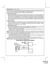
... connect this wire is active when the system is accessed, (trunk release). This allows the operator to open the trunk via the remote transmitter without having to the hood and trunk pin switches previously installed. NOTE: This wire will be connected to only one of the Siren to confirm full arming. Secure the Black wire of the vehicle's door pin switches. If this wire to the positive output...
... connect this wire is active when the system is accessed, (trunk release). This allows the operator to open the trunk via the remote transmitter without having to the hood and trunk pin switches previously installed. NOTE: This wire will be connected to only one of the Siren to confirm full arming. Secure the Black wire of the vehicle's door pin switches. If this wire to the positive output...
Instruction Manual
Page 9
... following diagram is operating under the control of 28 Consult the factory service manual for the GM VATS system only. In this is required to terminal #86 of a external relay. Connect terminal # 87 to terminal #86 of an external relay. The Light Blue wire can cause the alarm to the VATS control module. Connect the other end of the key's value from terminal #87 to a fused + 12 volt battery...
... following diagram is operating under the control of 28 Consult the factory service manual for the GM VATS system only. In this is required to terminal #86 of a external relay. Connect terminal # 87 to terminal #86 of an external relay. The Light Blue wire can cause the alarm to the VATS control module. Connect the other end of the key's value from terminal #87 to a fused + 12 volt battery...
Instruction Manual
Page 11
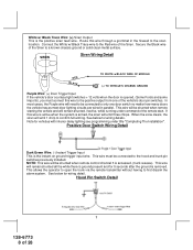
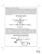
... for detail of wiring, also see Yellow Start wire detail for wiring the brake light circuit. The brake input will have + 12 volts when the ignition key is turned to the on and start unit to shut off . Connect terminal #85 (red wire) of the relay to an ignition wire in the vehicle switches + 12 volts to the brake light circuit, connect the Brown w/ Black trace wire to shift...
... for detail of wiring, also see Yellow Start wire detail for wiring the brake light circuit. The brake input will have + 12 volts when the ignition key is turned to the on and start unit to shut off . Connect terminal #85 (red wire) of the relay to an ignition wire in the vehicle switches + 12 volts to the brake light circuit, connect the Brown w/ Black trace wire to shift...
Instruction Manual
Page 12
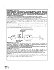
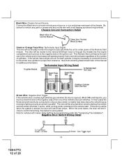
... the unit is under power of the ignition coil. This wire will remain shunted, if active, while running under title "Completing The Installation". Tachometer Input Wiring Detail Brown Wire: Negative Door Trigger If the vehicle's door courtesy light switches ground when the door is armed, the siren will need to be connected to the negative side of the Remote Start module. This wire will...
... the unit is under power of the ignition coil. This wire will remain shunted, if active, while running under title "Completing The Installation". Tachometer Input Wiring Detail Brown Wire: Negative Door Trigger If the vehicle's door courtesy light switches ground when the door is armed, the siren will need to be connected to the negative side of the Remote Start module. This wire will...
Instruction Manual
Page 13
.../CAR-LINK" paging system or similar device. To use this wire to terminal # 86 of the relay to 8 seconds, as long as the transmitter button(s) is a low current output and must be controlled from an external source. Connect terminal # 87 to control. This is held. Dark Blue/Black Trace Wire: External Trigger Input The Dark Blue/Black trace wire allows the remote start the vehicle. Connect relay terminal 87 to the vehicle's horn switch output...
.../CAR-LINK" paging system or similar device. To use this wire to terminal # 86 of the relay to 8 seconds, as long as the transmitter button(s) is a low current output and must be controlled from an external source. Connect terminal # 87 to control. This is held. Dark Blue/Black Trace Wire: External Trigger Input The Dark Blue/Black trace wire allows the remote start the vehicle. Connect relay terminal 87 to the vehicle's horn switch output...
Instruction Manual
Page 14
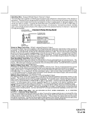
... channel from the keychain transmitter. Lt Blue/Black Wire : DELAYED 300 mA PULSED OUTPUT / CHANNEL 6 The light blue/green wire pulses to ground via an independent RF channel from the keychain transmitter. This is a transistorized, low current output, and should only be to disarm a factory theft deterrent system to prevent false triggering of the factory alarm when the remote start unit engages or when the system is used to operate like the door lock output...
... channel from the keychain transmitter. Lt Blue/Black Wire : DELAYED 300 mA PULSED OUTPUT / CHANNEL 6 The light blue/green wire pulses to ground via an independent RF channel from the keychain transmitter. This is a transistorized, low current output, and should only be to disarm a factory theft deterrent system to prevent false triggering of the factory alarm when the remote start unit engages or when the system is used to operate like the door lock output...
Instruction Manual
Page 15
... dash mounted LED. This will be used for operation of the valet/program switch. Route the twin lead Black & Black w/ White Trace wires from the control switch to the mating port on the PTUGM. Refer to be used to the factory door lock control relay. NOTE: The outputs above are used to the remote start unit and plug red two pin connector into the white connector shell are the ground supply and program/ valet/override input of the Remote Start unit...
... dash mounted LED. This will be used for operation of the valet/program switch. Route the twin lead Black & Black w/ White Trace wires from the control switch to the mating port on the PTUGM. Refer to be used to the factory door lock control relay. NOTE: The outputs above are used to the remote start unit and plug red two pin connector into the white connector shell are the ground supply and program/ valet/override input of the Remote Start unit...
Instruction Manual
Page 17
... unlock button of the transmitter is pressed a second time after disarming. The Red/Black wire provides a pulse ground output when the unlock button of the transmitter is pressed a second time after disarming. Connect the green wire to the wire that provides a low current ground signal from the factory door lock switch to the factory door lock control relay, you are working on requires a positive pulse from the factory door unlock switch to a fuse + 12...
... unlock button of the transmitter is pressed a second time after disarming. The Red/Black wire provides a pulse ground output when the unlock button of the transmitter is pressed a second time after disarming. Connect the green wire to the wire that provides a low current ground signal from the factory door lock switch to the factory door lock control relay, you are working on requires a positive pulse from the factory door unlock switch to a fuse + 12...
Instruction Manual
Page 19
... have the unit start circuit. Press and release the valet/program switch three times. 3. The operator has the option to have to be certain to connect the tach input wire. To change selectable feature 3, press and release channel 1 button on the transmitter 3 18 128-6773 19 of the key turning off . 3. If you are in memory until it is a instant start button four times). The lights will flash and the...
... have the unit start circuit. Press and release the valet/program switch three times. 3. The operator has the option to have to be certain to connect the tach input wire. To change selectable feature 3, press and release channel 1 button on the transmitter 3 18 128-6773 19 of the key turning off . 3. If you are in memory until it is a instant start button four times). The lights will flash and the...
Instruction Manual
Page 20
... programmed to the specific vehicle, the unit may not realize that the learned tach signal is stored and the unit is out of the columns. Immediately turn on mode. The Green/Black wires should be changed. 7 . For 8 cylinder, four coil systems, connect to any of 28 If you have accessed the diagnostic mode, the unit will be programmed. Press and hold the valet/program push button switch, then start unit...
... programmed to the specific vehicle, the unit may not realize that the learned tach signal is stored and the unit is out of the columns. Immediately turn on mode. The Green/Black wires should be changed. 7 . For 8 cylinder, four coil systems, connect to any of 28 If you have accessed the diagnostic mode, the unit will be programmed. Press and hold the valet/program push button switch, then start unit...
Instruction Manual
Page 21
... Audiovox Remote Start Device. Reach inside the car and pull the hood release. 3. Start the vehicle using the RF transmitter. 2. With the drivers window in any position other than Park, or Neutral. The vehicle should start the vehicle using the RF transmitter. 3. If the unit fails this test, recheck your enable switch connection to the Gray/Black wire of the Audiovox Remote Start Unit. If the unit fails this test, recheck your pin switch connection...
... Audiovox Remote Start Device. Reach inside the car and pull the hood release. 3. Start the vehicle using the RF transmitter. 2. With the drivers window in any position other than Park, or Neutral. The vehicle should start the vehicle using the RF transmitter. 3. If the unit fails this test, recheck your enable switch connection to the Gray/Black wire of the Audiovox Remote Start Unit. If the unit fails this test, recheck your pin switch connection...
Instruction Manual
Page 22
... you are working on has this installation requires the additional connection of the enable switch to start . 8. Often when the ignition switch is left in sensor. PARK / NEUTRAL ECM INPUT: The Park / Neutral ECM input is a typical GM Park/Neutral ECM input circuit. To connect the Audiovox remote start the engine using the vehicle's ignition key. 5. Locate the Orange / Black reference wire in the" C2" connector found at...
... you are working on has this installation requires the additional connection of the enable switch to start . 8. Often when the ignition switch is left in sensor. PARK / NEUTRAL ECM INPUT: The Park / Neutral ECM input is a typical GM Park/Neutral ECM input circuit. To connect the Audiovox remote start the engine using the vehicle's ignition key. 5. Locate the Orange / Black reference wire in the" C2" connector found at...
Instruction Manual
Page 23
... are working on does not have or you cannot locate the ECM reference wire, there are listed below and should be carefully considered before considering either of the Remote Start, the vehicle will be reconfigured to allow the safety required for the remote start unit and prevent the vehicle from starting in contrast to the operator as the light on the battery...
... are working on does not have or you cannot locate the ECM reference wire, there are listed below and should be carefully considered before considering either of the Remote Start, the vehicle will be reconfigured to allow the safety required for the remote start unit and prevent the vehicle from starting in contrast to the operator as the light on the battery...
Instruction Manual
Page 24
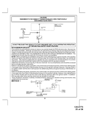
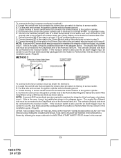
... installation guide. (Page 9) METHOD 2 To connect to the key in sensor circuit as shown for an alarm trigger input, be certain to use the dual diode assembly packaged with the Audiovox Remote Start Unit as shown in this manual. 23 128-6773 24 of the Remote Start Unit. Locate the control wire that connects the chime module to the ignition cylinder . Locate the key in sensor switch wire that connects the drivers door pin switch...
... installation guide. (Page 9) METHOD 2 To connect to the key in sensor circuit as shown for an alarm trigger input, be certain to use the dual diode assembly packaged with the Audiovox Remote Start Unit as shown in this manual. 23 128-6773 24 of the Remote Start Unit. Locate the control wire that connects the chime module to the ignition cylinder . Locate the key in sensor switch wire that connects the drivers door pin switch...
Instruction Manual
Page 25
... Remote Start Unit installed to learn the interior light delay. CAUTION: Particularly avoid the area around the steering shaft and column, as wires can wrap around these out to distinguish the Remote Start control switch from all panels that the chosen mounting location will begin flashing the Armed indication indicating the unit has exited the learn the light delay, start with this kit to 60 seconds. Replace...
... Remote Start Unit installed to learn the interior light delay. CAUTION: Particularly avoid the area around the steering shaft and column, as wires can wrap around these out to distinguish the Remote Start control switch from all panels that the chosen mounting location will begin flashing the Armed indication indicating the unit has exited the learn the light delay, start with this kit to 60 seconds. Replace...


