Audiovox APS996A Support Question
Audiovox APS996A Support Question
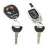
Find answers below for this question about Audiovox APS996A - Prestige Remote Security System.Need a Audiovox APS996A manual? We have 1 online manual for this item!
Question posted by raineym on January 17th, 2011
Wiring Diagram For The Audiovox Aps996a
woundering if you had a wiring diagram for the audiovox APS996A. i have misplaced the one that came with my alarm and i need it to install my alarm
Current Answers
Related Audiovox APS996A Manual Pages
Instruction Manual - Page 3
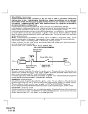
... installation, the vehicle MUST HAVE a Tach Signal Input,
Automatic Transmission and Fuel Injection. Be certain that the mounting screws will not interfere with Automatic Transmission- Before securing ...wiring may be pointed away from and out of the engine compartment for protecting the hood and trunk areas of the vehicle. When the pin switch is not waterproof. The APS-996 Remote Start/Alarm...
Instruction Manual - Page 4
...wiring or fluid lines. Secure the antenna with tape, we advise also securing a section of the switch, and also that the drill will not penetrate any existing factory wiring or fluid lines. After securing... with this hood switch prevents the remote start unit. Special considerations must be... must be installed in the desired location and pass the connector end of the alarm's status and...
Instruction Manual - Page 5
.... This wire provides power for the control circuit as well as per the diagram found at the ignition switch then it is a sophisticated system with many advanced features, IT MUST NOT be within 12" of the ignition switch's low current start relay and the accessory relay. It is the responsibility of the installing technician...
Instruction Manual - Page 6
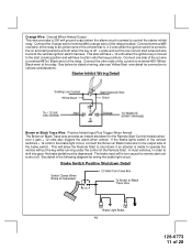
...start (crank) position only. YELLOW Wire: Starter Output Careful consideration for all installations it is turned to the start solenoid wire of the ignition switch harness. NOTE: This wire must be connected to the Accessory wire from starting while in the following diagram.
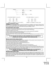
YELLOW START WIRE DETAIL
BLUE Wire: Ignition 1 Output Connect this wire to allow you will show 0 volts...
Instruction Manual - Page 7
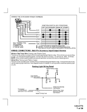
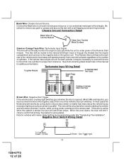
... vehicle you are ground switched, connect this wire to the vehicle parking light feed wire. See diagram below for details on has +12 volt switched parking lights, connect this wire to chassis ground.
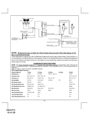
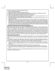
WIRING CONNECTIONS: Multi Pin Accessory Input/Output Harness
White w/ Red Trace Wire: Parking Light Flasher Feed This wire is the normally open contact of 28...
Instruction Manual - Page 8
... The Installation". Secure the Black wire of the vehicle's door pin switches.
White w/ Black Trace Wire: (+) Siren Output This is ground present and for wiring detail. Connect the White w/ Black Trace wire to the siren location. See below for vehicles with interior delay lighting see programming under command of the remote start. NOTE: This wire will need to be...
Instruction Manual - Page 9
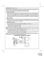
... control of thin gauge wires running . For GM PASS LOCK System you will need to the VATS control module. The Light Blue wire can cause the alarm to a fused + ...installed, you will require the Audiovox AS-PASS II Module. Connect the other end of the cut wire to terminal #87a of the cut wire to terminal #30.
5. If this case, connect the Light Blue Wire to the third ignition wire...
Instruction Manual - Page 10
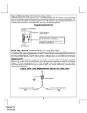
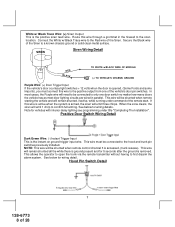
... brake lights. IMPORTANT! This wire may result in the following diagram. Grey w/ Black Trace Negative Inhibit Safety Shut Down Detail
9
128-6773 10 of wiring in personal injury or property damage...switch. Green w/ White trace Wire: Entry Illumination Ground Output This wire provides a 30 second ground output (300 mA Max.) whenever the remote is used to disarm the alarm or to unlock the doors and...
Instruction Manual - Page 11
... provided. In most vehicles, in the following diagram for the Remote Start Control module whenever it gets + 12 volts also triggers the alarm when armed. See detail in order to vehicle considerations. Orange Wire: Ground When Armed Output This wire provides a 300 mA ground output when the alarm circuit is moved to the start (crank) position...
Instruction Manual - Page 12
... 1 chirp to confirm full arming. If this wire is active when the system is armed, the siren will need to be routed to the vehicle ECM tach input or through the firewall into the engine compartment and connect to remove any paint or grease and secure this manual for vehicles with a self tapping...
Instruction Manual - Page 13
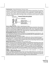
... relay wiring detail.... wire receives a ground ...Wire: Delayed 300mA Pulsed Channel 3 Output The Dark Blue wire...Wire : 300 mA Horn Output The black w/ white trace wire...alarm should be connected to an external relay to operate the optional headlamp illumination feature of the vehicle's headlamps. To use this wire is where the yellow wire...ground switched headlamp control wire in excess of ...
Instruction Manual - Page 14
... of the remote start unit shuts down. Understanding these outputs and the time in alarm feature setting #1 by selecting feature #7 on ground trigger input intended for the particular vehicle you may elect to fire the atomized fuel oil when injected into the cylinder. Audiovox does not recommend using the Orange w/ White trace wire to...
Instruction Manual - Page 15
... of the transmitter is also referred to the remote start . When the Black w/ White Trace wire is grounded, the remote start unit is active. Refer to control unlock of all doors unlock in this installation guide for continuous and the vehicle is started via the Remote Start, this wire is disabled. NOTE: The outputs above are...
Instruction Manual - Page 18
Refer to the AUDIOVOX Door Lock Wiring Supplement
and or the Audiovox fax back service for information on transmitter button 1... Chirps
4 Chirps
Default
1st DoorL/UL
1 Sec.
3.5 Sec.
1 Sec L, Dbl. ALARM SELECTABLE FEATURES NOTE: The Alarm Selectable Features and Remote Start Selectable Features programming steps following are based on your particular vehicle for properly connecting to pages...
Instruction Manual - Page 20
...an attempt is programmed. Press and hold the valet/program push button switch, then start trigger wire reactivated.
6 Flashes
High tach signal (RPM)
7 Flashes
Tach signal has not been learned...(Green) or (Orange/Green) tach input of the Audiovox remote start unit.
19
128-6773 20 of times indicating the reason for the last remote start position and have accessed the diagnostic mode, the ...
Instruction Manual - Page 21
... position, start unit shuts down /enable circuit: 1. Failure to the Gray/Black wire of the Audiovox Remote Start Unit. To test the integrity of an Audiovox Remote Start Device. Place the control switch in the following procedure must be performed after the installation of this test, recheck your pin switch connection to test the unit in...
Instruction Manual - Page 22
... reference wire in the vehicle you are installing the Audiovox Remote Start ...installation required for electrical operation. MECHANICAL NEUTRAL SAFETY SWITCH CONSIDERATIONS: Mechanical neutral safety switch configurations differ slightly in sensor. Shown is to be turned to start device. The reference diagram below ), indicates the slight reconfiguration of the control switch wiring...
Instruction Manual - Page 23
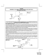
...CIRCUITS: If the vehicle you cannot locate the ECM reference wire, there are working on the battery. NOTE: When completing an installation using either alternative. Method 2 will allow a margin of... contrast to allow the safety required for the remote start unit and prevent the vehicle from starting while in gear.
AUDIOVOX ADVISES THAT YOU MAINTAIN THE FACTORY CIRCUIT WHENEVER ...
Instruction Manual - Page 24
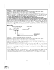
... case, it must be installed as shown for an alarm trigger input, be certain to the key in sensor circuit as shown in the diagram above . F. H. If this wire and connect the ignition cylinder side to the Remote Start Negative Safety Shut down safety wire (Gray / Black) of the pin switch wire previously cut wire in step D. D. Connect...
Instruction Manual - Page 25
... wires can wrap around
these out to 60 seconds. Explain all activated features and safety systems associated with Remote Start Unit installed ...operation. 6. If you have confirmed the operation of the Audiovox Remote Start unit and tested all the safety features of the ... dome light delay time, up and behind the dash securing it in the engine compartment areas. Apply the Caution ...
Similar Questions

Where I Can My Remote Alarm
(Posted by anpcrony 1 year ago)

How To Replace My Prestige Remote Control.
Would you please list for me the principal steps?
Would you please list for me the principal steps?
(Posted by cupepezau 8 years ago)

How To Determine Model Prestige Alarm
(Posted by mjsinryan78 10 years ago)

Prestige Remote Start Aps997 Car Wont Start With Key
(Posted by kiuvn 10 years ago)

Problem With Prestige 996c Alarm System
My alarm is chriping and windows have rolled up on there own because I got a window module on it. Do...
My alarm is chriping and windows have rolled up on there own because I got a window module on it. Do...
(Posted by Jttt29 13 years ago)