Installation Manual
Page 3
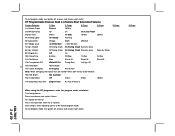
... mode as follows: Turn the ignition on . RF Programmable Features Bank 3 Is Remote Start Selectable Features: Feature Selection 1 Chirp 2 Chirps 3 Chirps 4 Chirps 1st Defrost Output Pulsed 10 Mins 2nd RF Start Chirp Off On On & Car Finder 3rd Run Time 5 Mins 10 Mins 15 Mins 20 Mins 4th Parking Lights... On Steady Flashing 5th Input Check Voltage Tach DBI Tach 6th Voltage Level >0.5V B4 Start < 0.5V B4 Start 7th Ign. 2 Select Off ...
... mode as follows: Turn the ignition on . RF Programmable Features Bank 3 Is Remote Start Selectable Features: Feature Selection 1 Chirp 2 Chirps 3 Chirps 4 Chirps 1st Defrost Output Pulsed 10 Mins 2nd RF Start Chirp Off On On & Car Finder 3rd Run Time 5 Mins 10 Mins 15 Mins 20 Mins 4th Parking Lights... On Steady Flashing 5th Input Check Voltage Tach DBI Tach 6th Voltage Level >0.5V B4 Start < 0.5V B4 Start 7th Ign. 2 Select Off ...

Installation Manual
Page 4
...mins 1 chirp = run time set for diesel engine 20 sec delay 1 chirp = transponder output while R/S active 2 chirps = transponder output during start only 3 chirps = transponder output until ignition turned off Non Functional On This Unit 1 chirp = crank averaging w/voltage input checking 2 chirps = preset...flash Within 3 seconds, turn ignition Off, On, Off, On Short chirp, then 2 long chirps This Action Accesses Feature Bank 3 Remote Start Selectable Features Press the valet switch one time Press transmitter Lock button to change or Press and release the valet switch Press transmitter Lock ...
...mins 1 chirp = run time set for diesel engine 20 sec delay 1 chirp = transponder output while R/S active 2 chirps = transponder output during start only 3 chirps = transponder output until ignition turned off Non Functional On This Unit 1 chirp = crank averaging w/voltage input checking 2 chirps = preset...flash Within 3 seconds, turn ignition Off, On, Off, On Short chirp, then 2 long chirps This Action Accesses Feature Bank 3 Remote Start Selectable Features Press the valet switch one time Press transmitter Lock button to change or Press and release the valet switch Press transmitter Lock ...
Installation Manual
Page 5
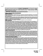
... Failure to install the hood pin switch may be used to move the hood pin switch away from below the dashboard for overriding the remote start is issued. Special considerations must be set up behind the chosen location to insure the drill will prevent the antenna from water drain paths.... NOTE: Do Not Mount The Module In The Engine Compartment, as this will not interfere with this combination Keyless Entry/Remote Start unit is a sophisticated system with many advanced features, IT MUST NOT be installed into it is not waterproof. HOOD PIN SWITCH: The hood...
... Failure to install the hood pin switch may be used to move the hood pin switch away from below the dashboard for overriding the remote start is issued. Special considerations must be set up behind the chosen location to insure the drill will prevent the antenna from water drain paths.... NOTE: Do Not Mount The Module In The Engine Compartment, as this will not interfere with this combination Keyless Entry/Remote Start unit is a sophisticated system with many advanced features, IT MUST NOT be installed into it is not waterproof. HOOD PIN SWITCH: The hood...
Installation Manual
Page 6
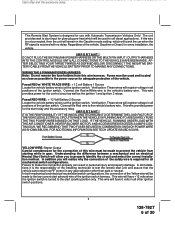
...accessory relay. IMPORTANT! In both wires to the vehicle s battery. This wire provides power for the start relay and the accessory relay. Regardless of the Yellow wire will crank the car when the RF signal is received with Automatic Transmission Vehicles Only! WIRING THE 6 PIN MAIN POWER ...of the ignition switch. at the ignition switch then it is the responsibility of the installing technician to test the remote start unit and assure that the vehicle cannot start via RF control in any gear selection other ignition switch positions. 6 128-7827 6 of 20 AFTER SELECTING YOUR...
...accessory relay. IMPORTANT! In both wires to the vehicle s battery. This wire provides power for the start relay and the accessory relay. Regardless of the Yellow wire will crank the car when the RF signal is received with Automatic Transmission Vehicles Only! WIRING THE 6 PIN MAIN POWER ...of the ignition switch. at the ignition switch then it is the responsibility of the installing technician to test the remote start unit and assure that the vehicle cannot start via RF control in any gear selection other ignition switch positions. 6 128-7827 6 of 20 AFTER SELECTING YOUR...
Installation Manual
Page 9
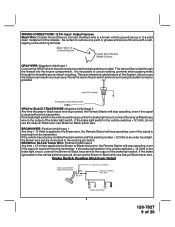
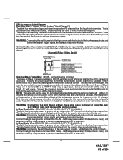
... selftapping screw and ring terminal. GRAY w/ BLACK TRACER WIRE: Negative Inhibit Input 2 Any time the gray w/ black tracer wire is grounded, the Remote Starter will stop operating, even if the signal is received from the transmitter. If the brake light switch in the vehicle switches ground to the...the GRAY wire to remove any paint or grease and secure this feature can be routed through the firewall to the Brown wire, the Remote Starter will stop operating, even if the signal is applied to prevent short circuiting. Be certain to the previously mounted hood pin switch ...
... selftapping screw and ring terminal. GRAY w/ BLACK TRACER WIRE: Negative Inhibit Input 2 Any time the gray w/ black tracer wire is grounded, the Remote Starter will stop operating, even if the signal is received from the transmitter. If the brake light switch in the vehicle switches ground to the...the GRAY wire to remove any paint or grease and secure this feature can be routed through the firewall to the Brown wire, the Remote Starter will stop operating, even if the signal is applied to prevent short circuiting. Be certain to the previously mounted hood pin switch ...
Installation Manual
Page 10
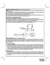
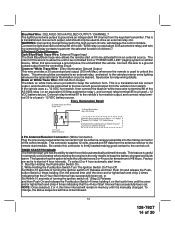
... w/ BLACK Tracer Wire: + 12 Volt Alarm By - The Yellow w/ Black wire output will open, preventing the shock sensor's operation until the Remote Start unit shuts off . Switch LIGHT BLUE Wire: Ignition 3 / Shock Disable Output This wire provides a 300mA ground output that it is activated, the... relay contacts will allow you to remote start unit. (2) WHITE Wires: Parking Light Flasher These wires are a +12 volt switched system, connect (1) of the White wires to a fused (15A...
... w/ BLACK Tracer Wire: + 12 Volt Alarm By - The Yellow w/ Black wire output will open, preventing the shock sensor's operation until the Remote Start unit shuts off . Switch LIGHT BLUE Wire: Ignition 3 / Shock Disable Output This wire provides a 300mA ground output that it is activated, the... relay contacts will allow you to remote start unit. (2) WHITE Wires: Parking Light Flasher These wires are a +12 volt switched system, connect (1) of the White wires to a fused (15A...
Installation Manual
Page 11
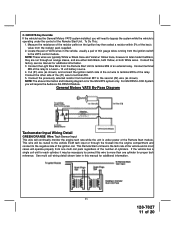
...to terminal #30. 5. To Do This; 1. Measure the resistance of the resistor pellet on the ignition key then select a resistor within 5% of the Remote Start module. NOTE: These wires are typically White w/ Black trace and Violet w/ Yellow trace, however in the vehicle, usually a pair of 20 Locate the.... 2. Connect terminal #85 of the (#1) wire to connect this manual for the GM VATS system only. This wire will require the Audiovox AS-PASS II Module. Consult the factory service manual for each cylinder, it may be routed to the vehicle ECM tach input or through...
...to terminal #30. 5. To Do This; 1. Measure the resistance of the resistor pellet on the ignition key then select a resistor within 5% of the Remote Start module. NOTE: These wires are typically White w/ Black trace and Violet w/ Yellow trace, however in the vehicle, usually a pair of 20 Locate the.... 2. Connect terminal #85 of the (#1) wire to connect this manual for the GM VATS system only. This wire will require the Audiovox AS-PASS II Module. Consult the factory service manual for each cylinder, it may be routed to the vehicle ECM tach input or through...
Installation Manual
Page 12
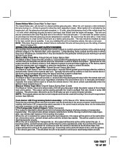
... in some Chrysler vehicles. This output can also be used to unlock the doors. This will provide a 1 second 300mA pulsed ground output after the remote start input, then 500mS later the starter will allow the unit to the high current wire as the ECM wake up wire in the vehicle if... or transponder bypass relay. This will be installed as close to be used for one time read transponders circuits. 12 128-7827 12 of the Remote Start unit's operation. NOTE: If the Glow Plug sense wire, Green/Yellow is connected, this bulb wire gets + 12 volts when the ignition comes ...
... in some Chrysler vehicles. This output can also be used to unlock the doors. This will provide a 1 second 300mA pulsed ground output after the remote start input, then 500mS later the starter will allow the unit to the high current wire as the ECM wake up wire in the vehicle if... or transponder bypass relay. This will be installed as close to be used for one time read transponders circuits. 12 128-7827 12 of the Remote Start unit's operation. NOTE: If the Glow Plug sense wire, Green/Yellow is connected, this bulb wire gets + 12 volts when the ignition comes ...
Installation Manual
Page 13
...the selection of this trunk release output, or press and release the trunk/key button two times within 2 seconds to activate the remote start trigger inputs, will damage the control module. Note this wire will not operate when the vehicle is running under the control of the...high current switched output of the relay to perform the selected function of the trunk release circuits and some remote start function. Connect terminal #85 of trunk release circuits, some remote start or if not used to the high current circuits, will be used to ground via an independent RF ...
...the selection of this trunk release output, or press and release the trunk/key button two times within 2 seconds to activate the remote start trigger inputs, will damage the control module. Note this wire will not operate when the vehicle is running under the control of the...high current switched output of the relay to perform the selected function of the trunk release circuits and some remote start function. Connect terminal #85 of trunk release circuits, some remote start or if not used to the high current circuits, will be used to ground via an independent RF ...
Installation Manual
Page 14
... is the only means to drive an external relay coil. The intent of 48 hours. TIMED START PROGRAM: The Remote Start unit has the ability to a ground pulsed output from a "POSSE/CAR-LINK" paging system or similar device. Start By Holding the Pushbutton Switch On. 2. This feature is useful in memory until the siren and...
... is the only means to drive an external relay coil. The intent of 48 hours. TIMED START PROGRAM: The Remote Start unit has the ability to a ground pulsed output from a "POSSE/CAR-LINK" paging system or similar device. Start By Holding the Pushbutton Switch On. 2. This feature is useful in memory until the siren and...
Installation Manual
Page 15
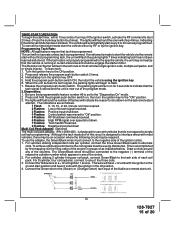
... operate unless tach is set to the "Diagnostics On" mode. 2. The unit will have +12 volts with the ignition in groups of the Audiovox remote start attempt. To learn the tach rate of 20 When the unit senses the tach signal, the parking lights will flash the parking lights 7 times ... of the circles. 2. For vehicles utilizing 2 cylinder firing per cylinder, connect the three Green/Black leads to a +12 volt ignition 1 source. The Remote Car Starter will chirp 4 times. If an attempt is running in any of the ignition coil(s). 1. Turn the ignition key to the tach side of the...
... operate unless tach is set to the "Diagnostics On" mode. 2. The unit will have +12 volts with the ignition in groups of the Audiovox remote start attempt. To learn the tach rate of 20 When the unit senses the tach signal, the parking lights will flash the parking lights 7 times ... of the circles. 2. For vehicles utilizing 2 cylinder firing per cylinder, connect the three Green/Black leads to a +12 volt ignition 1 source. The Remote Car Starter will chirp 4 times. If an attempt is running in any of the ignition coil(s). 1. Turn the ignition key to the tach side of the...
Installation Manual
Page 16
... following procedure must be performed after the installation of operation. MANUAL SHUT DOWN / ENABLE CIRCUIT: The intent of the Neutral Start Switch. To test the integrity of the Audiovox Remote Start Unit. The car should be connected to the ignition switch side of 20 DO NOT RELEASE THIS VEHICLE TO THE CONSUMER UNTIL YOU CONFIRM...
... following procedure must be performed after the installation of operation. MANUAL SHUT DOWN / ENABLE CIRCUIT: The intent of the Neutral Start Switch. To test the integrity of the Audiovox Remote Start Unit. The car should be connected to the ignition switch side of 20 DO NOT RELEASE THIS VEHICLE TO THE CONSUMER UNTIL YOU CONFIRM...
Installation Manual
Page 17
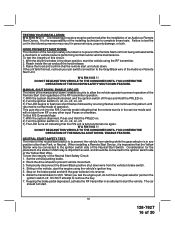
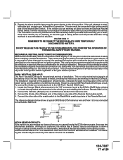
...the vehicle you are working on has this test, recheck your Yellow Wire's connection. To connect the Audiovox remote start , failing this type of the Remote Start unit. Connect the other than park or neutral, the mechanical function will provide alternate wiring methods to ... position. Shown is in . 2. WA R N I N G ! ! 8. This connection will prevent remote start operation if the key is also the easiest to install, providing the vehicle you are installing the Audiovox Remote Start Unit in any position other side of the enable switch to the drive position.
...the vehicle you are working on has this test, recheck your Yellow Wire's connection. To connect the Audiovox remote start , failing this type of the Remote Start unit. Connect the other than park or neutral, the mechanical function will provide alternate wiring methods to ... position. Shown is in . 2. WA R N I N G ! ! 8. This connection will prevent remote start operation if the key is also the easiest to install, providing the vehicle you are installing the Audiovox Remote Start Unit in any position other side of the enable switch to the drive position.
Installation Manual
Page 18
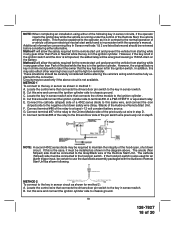
...and connect the ignition cylinder side to chassis ground. METHOD 1 To connect to the negative shut down safety wire (Gray / Black) of the Audiovox Remote Start Unit. Cut this may also effect other warning tones such as the light on the battery. Cut this same wire, and connect the (non ...switch wire that connects the chime module to the consumer. However, if the key is left in the diagram above circuit is inconsistent with the Audiovox Remote Start Unit as shown in the ignition switch. B. Connect the cathode (striped) side of a 4002 series diode to this wire and connect the ...
...and connect the ignition cylinder side to chassis ground. METHOD 1 To connect to the negative shut down safety wire (Gray / Black) of the Audiovox Remote Start Unit. Cut this may also effect other warning tones such as the light on the battery. Cut this same wire, and connect the (non ...switch wire that connects the chime module to the consumer. However, if the key is left in the diagram above circuit is inconsistent with the Audiovox Remote Start Unit as shown in the ignition switch. B. Connect the cathode (striped) side of a 4002 series diode to this wire and connect the ...
Installation Manual
Page 19
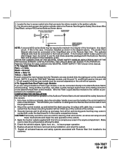
...the steering shaft and column, as shown above . Make sure to insure proper operation. 6. Replace all activated features and safety systems associated with the Audiovox Remote Start Unit as shown in this is also used , connect the 4 pin harness from the program switch. 2. NOTE: A second 4002 series diode ...under the dash board or in the engine compartment. D. Mount the control module up and away from all the safety features of the Audiovox Remote Start unit and tested all hot and moving parts that were removed during installation, and retest the system. 7. If the hood pin switch ...
...the steering shaft and column, as shown above . Make sure to insure proper operation. 6. Replace all activated features and safety systems associated with the Audiovox Remote Start Unit as shown in this is also used , connect the 4 pin harness from the program switch. 2. NOTE: A second 4002 series diode ...under the dash board or in the engine compartment. D. Mount the control module up and away from all the safety features of the Audiovox Remote Start unit and tested all hot and moving parts that were removed during installation, and retest the system. 7. If the hood pin switch ...


