
Motherboard DIY Troubleshooting Guide
Page 4
Safeguards Contents 2.4.3 Integrated Peripherals 2-18 2.4.4 Power Management Setup 2-20 2.4.5 PnP / PCI Configurations 2-22 2.5 Security Menu 2-23 2.6 Hardware Monitor Menu 2-24 2.7 Exit Menu 2-26 Chapter 3: Starting Up 3.1 Install an operating system 3-2 3.2 Support CD information 3-2 3.2.1 Running the support CD 3-2 3.2.2 Drivers menu 3-3 3.2.3 Utilities menu 3-3 3.2.4 ASUS Contact Information 3-4 iv
Safeguards Contents 2.4.3 Integrated Peripherals 2-18 2.4.4 Power Management Setup 2-20 2.4.5 PnP / PCI Configurations 2-22 2.5 Security Menu 2-23 2.6 Hardware Monitor Menu 2-24 2.7 Exit Menu 2-26 Chapter 3: Starting Up 3.1 Install an operating system 3-2 3.2 Support CD information 3-2 3.2.1 Running the support CD 3-2 3.2.2 Drivers menu 3-3 3.2.3 Utilities menu 3-3 3.2.4 ASUS Contact Information 3-4 iv
Motherboard DIY Troubleshooting Guide
Page 9
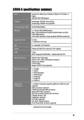
... 8X (1.5V only) 2 x UltraDMA 133/100/66/33 Realtek ALC650 6CH with built-in HP amplifier 1 Port MCP integrated NVIDIA MAC + Realtek 8201BL PHY ASUS Q-Fan Technology ASUS C.O.P. (CPU Overheating Protection) Power Loss Restart CPU Throttle Support S/PDIF in/out (optional) 1 x Parallel 1 x Serial 1 x PS/2 Keyboard 1 x PS/2 Mouse 1 x RJ45 port 1 x Audio I/O 4 x USB 2.0 1 x USB 2.0 connector...
... 8X (1.5V only) 2 x UltraDMA 133/100/66/33 Realtek ALC650 6CH with built-in HP amplifier 1 Port MCP integrated NVIDIA MAC + Realtek 8201BL PHY ASUS Q-Fan Technology ASUS C.O.P. (CPU Overheating Protection) Power Loss Restart CPU Throttle Support S/PDIF in/out (optional) 1 x Parallel 1 x Serial 1 x PS/2 Keyboard 1 x PS/2 Mouse 1 x RJ45 port 1 x Audio I/O 4 x USB 2.0 1 x USB 2.0 connector...
Motherboard DIY Troubleshooting Guide
Page 10
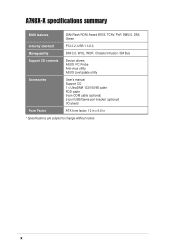
x Manageability DMI 2.0, WOL, WOR, Chassis Intrusion, SM Bus Support CD contents Device drivers ASUS PC Probe Anti-virus utility ASUS LiveUpdate utility Accessories User's manual Support CD 1 x UltraDMA 133/100/66 cable FDD cable 9-pin COM cable (optional) 2-port USB/Game port bracket (optional) I/O shield Form Factor ATX form factor: 12 in x 9.6 in * Specifications are subject to change without notice. A7N8X-X specifications summary BIOS features 2Mb Flash ROM, Award BIOS, TCAV, PnP, DMI2.0, DMI, Green Industry standard PCI 2.2, USB 1.1/2.0.
x Manageability DMI 2.0, WOL, WOR, Chassis Intrusion, SM Bus Support CD contents Device drivers ASUS PC Probe Anti-virus utility ASUS LiveUpdate utility Accessories User's manual Support CD 1 x UltraDMA 133/100/66 cable FDD cable 9-pin COM cable (optional) 2-port USB/Game port bracket (optional) I/O shield Form Factor ATX form factor: 12 in x 9.6 in * Specifications are subject to change without notice. A7N8X-X specifications summary BIOS features 2Mb Flash ROM, Award BIOS, TCAV, PnP, DMI2.0, DMI, Green Industry standard PCI 2.2, USB 1.1/2.0.
Motherboard DIY Troubleshooting Guide
Page 12
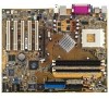
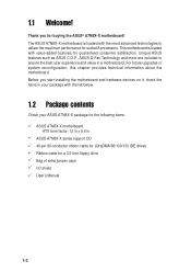
...system reconfiguration, this chapter provides technical information about the motherboard. The ASUS A7N8X-X motherboard is loaded with the most advanced technologies to ensure the best user experience and value in ASUS A7N8X-X series support CD 40-pin 80-conductor ribbon cable for UltraDMA/66/100/133... IDE drives Ribbon cable for socket A processors. This motherboard is loaded with value-added features for buying the ASUS® A7N8X-X motherboard! 1.1 Welcome...
...system reconfiguration, this chapter provides technical information about the motherboard. The ASUS A7N8X-X motherboard is loaded with the most advanced technologies to ensure the best user experience and value in ASUS A7N8X-X series support CD 40-pin 80-conductor ribbon cable for UltraDMA/66/100/133... IDE drives Ribbon cable for socket A processors. This motherboard is loaded with value-added features for buying the ASUS® A7N8X-X motherboard! 1.1 Welcome...
Motherboard DIY Troubleshooting Guide
Page 14
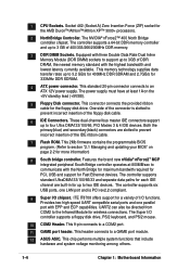
... Rate Dual Inline Memory Module (DDR DIMM) sockets to support up to 3GB of the IDE ribbon cable. 7 Flash ROM. ITE IT8708 offers support for 333MHz DDR SDRAM. 4 ATX power connector. This 9-pin connects to a GAME port module. 12 ASUS ASIC. The power supply must have at 800MB/sec to... two IDE devices. These dual-channel bus master IDE connectors support up to communicate with EPP and ECP capabilities. This 2Mb firmware contains the programmable BIOS ...
... Rate Dual Inline Memory Module (DDR DIMM) sockets to support up to 3GB of the IDE ribbon cable. 7 Flash ROM. ITE IT8708 offers support for 333MHz DDR SDRAM. 4 ATX power connector. This 9-pin connects to a GAME port module. 12 ASUS ASIC. The power supply must have at 800MB/sec to... two IDE devices. These dual-channel bus master IDE connectors support up to communicate with EPP and ECP capabilities. This 2Mb firmware contains the programmable BIOS ...
Motherboard DIY Troubleshooting Guide
Page 15
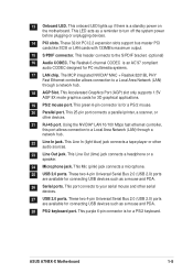
...133MB/s maximum output. 15 S/PDIF connector. This header connects to turn off the system power before plugging or unplugging devices. 14 PCI slots. ASUS A7N8X-X Motherboard 1-5 13 Onboard LED. This onboard LED lights up if there is for 3D graphical applications. 19 PS/2 mouse port. This .... This Line In (light blue) jack connects a tape player or other devices. 21 RJ-45 port. This Accelerated Graphics Port (AGP) slot only supports 1.5V AGP 8X mode graphics cards for a PS/2 mouse. 20 Parallel port. This port connects to a Local Area Network (LAN) through a network...
...133MB/s maximum output. 15 S/PDIF connector. This header connects to turn off the system power before plugging or unplugging devices. 14 PCI slots. ASUS A7N8X-X Motherboard 1-5 13 Onboard LED. This onboard LED lights up if there is for 3D graphical applications. 19 PS/2 mouse port. This .... This Line In (light blue) jack connects a tape player or other devices. 21 RJ-45 port. This Accelerated Graphics Port (AGP) slot only supports 1.5V AGP 8X mode graphics cards for a PS/2 mouse. 20 Parallel port. This port connects to a Local Area Network (LAN) through a network...
Motherboard DIY Troubleshooting Guide
Page 17
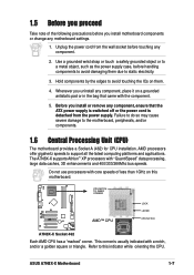
... data caches, 3D enhancements and 400/333/266Mhz bus speeds. This corner is detached from the wall socket before touching any motherboard settings. 1. ASUS A7N8X-X Motherboard 1-7 The A7N8X-X supports Athlon™ XP processors with a notch, and/or a golden square or triangle. Do not use processors with core speeds of the following precautions...) for CPU installation. Unplug the power cord from the power supply. Hold components by the edges to avoid touching the ICs on them due to support all the latest computing platforms and applications.
... data caches, 3D enhancements and 400/333/266Mhz bus speeds. This corner is detached from the wall socket before touching any motherboard settings. 1. ASUS A7N8X-X Motherboard 1-7 The A7N8X-X supports Athlon™ XP processors with a notch, and/or a golden square or triangle. Do not use processors with core speeds of the following precautions...) for CPU installation. Unplug the power cord from the power supply. Hold components by the edges to avoid touching the ICs on them due to support all the latest computing platforms and applications.
Motherboard DIY Troubleshooting Guide
Page 18
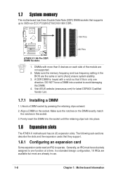
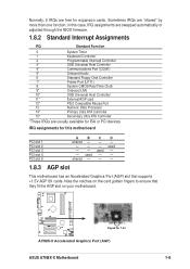
...an IRQ must be exclusively assigned to one direction. 1.7 System memory The motherboard has three Double Data Rate (DDR) DIMM sockets that they support. 1.8.1 Configuring an expansion card Some expansion cards need an IRQ to operate. Make sure the memory frequency and bus frequency setting in the ...socket. 3. DO NOT force a DIMM into place. 1.8 Expansion slots The A7N8X-X motherboard has six (6) expansion slots. Visit ASUS website (www.asus.com) for latest DDR400 Qualified Vendor List. 1.7.1 Installing a DIMM 1. Align a DIMM on each side of the module are the same or...
...an IRQ must be exclusively assigned to one direction. 1.7 System memory The motherboard has three Double Data Rate (DDR) DIMM sockets that they support. 1.8.1 Configuring an expansion card Some expansion cards need an IRQ to operate. Make sure the memory frequency and bus frequency setting in the ...socket. 3. DO NOT force a DIMM into place. 1.8 Expansion slots The A7N8X-X motherboard has six (6) expansion slots. Visit ASUS website (www.asus.com) for latest DDR400 Qualified Vendor List. 1.7.1 Installing a DIMM 1. Align a DIMM on each side of the module are the same or...
Motherboard DIY Troubleshooting Guide
Page 19
...) slot that they fit the AGP slot on the card golden fingers to ensure that supports +1.5V AGP 8X cards. Note the notches on your motherboard. ® A7N8X-X Keyed for 1.5v A7N8X-X Accelerated Graphics Port (AGP) ASUS A7N8X-X Motherboard 1-9 in this case, IRQ assignments are swapped automatically or adjusted through the BIOS...
...) slot that they fit the AGP slot on the card golden fingers to ensure that supports +1.5V AGP 8X cards. Note the notches on your motherboard. ® A7N8X-X Keyed for 1.5v A7N8X-X Accelerated Graphics Port (AGP) ASUS A7N8X-X Motherboard 1-9 in this case, IRQ assignments are swapped automatically or adjusted through the BIOS...
Motherboard DIY Troubleshooting Guide
Page 20
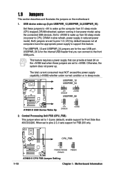
... connected USB devices. This feature requires a power supply that you can provide at least 2A on the motherboard. 1. When set to 1-2 pins (default), enable support for FSB 200 only. ® A7N8X-X CPU_FSB 1 2 FSB400/333/266 (Default) 2 3 FSB200 1-10 A7N8X-X CPU FSB Jumper Setting Chapter 1: Motherboard ...reduced power mode). Both jumpers are set to pins 1-2 (+5V) by default because not all computers have the appropriate power supply to support this feature. The USBPWR_12 and USBPWR_34 jumpers are for the internal USB header that can connect to the front USB ports. Otherwise, ...
... connected USB devices. This feature requires a power supply that you can provide at least 2A on the motherboard. 1. When set to 1-2 pins (default), enable support for FSB 200 only. ® A7N8X-X CPU_FSB 1 2 FSB400/333/266 (Default) 2 3 FSB200 1-10 A7N8X-X CPU FSB Jumper Setting Chapter 1: Motherboard ...reduced power mode). Both jumpers are set to pins 1-2 (+5V) by default because not all computers have the appropriate power supply to support this feature. The USBPWR_12 and USBPWR_34 jumpers are for the internal USB header that can connect to the front USB ports. Otherwise, ...
Motherboard DIY Troubleshooting Guide
Page 22
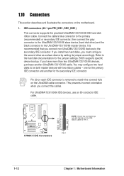
one for the primary IDE connector and another UltraDMA/133/100/66 cable. BIOS supports specific device bootup. This prevents incorrect orientation when you connect non-UltraDMA/133/100/66 devices to match the covered hole on each IDE connector ... (hard disk drive) and the black connector to the hard disk documentation for the secondary IDE connector. IDE connectors (40-1 pin PRI_IDE1, SEC_IDE1) This connector supports the provided UltraDMA/133/100/66 IDE hard disk ribbon cable.
one for the primary IDE connector and another UltraDMA/133/100/66 cable. BIOS supports specific device bootup. This prevents incorrect orientation when you connect non-UltraDMA/133/100/66 devices to match the covered hole on each IDE connector ... (hard disk drive) and the black connector to the hard disk documentation for the secondary IDE connector. IDE connectors (40-1 pin PRI_IDE1, SEC_IDE1) This connector supports the provided UltraDMA/133/100/66 IDE hard disk ribbon cable.
Motherboard DIY Troubleshooting Guide
Page 23
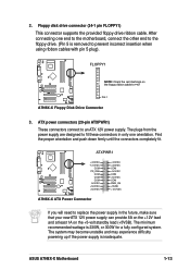
... standby lead (+5VSB). Find the proper orientation and push down firmly until the connectors completely fit. 2. Floppy disk drive connector (34-1 pin FLOPPY1) This connector supports the provided floppy drive ribbon cable. The minimum recommended wattage is inadequate. After connecting one orientation. The plugs from the power supply are designed to...
... standby lead (+5VSB). Find the proper orientation and push down firmly until the connectors completely fit. 2. Floppy disk drive connector (34-1 pin FLOPPY1) This connector supports the provided floppy drive ribbon cable. The minimum recommended wattage is inadequate. After connecting one orientation. The plugs from the power supply are designed to...
Motherboard DIY Troubleshooting Guide
Page 24
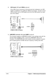
GAME/MIDI connector (16-1 pin GAME1) (optional) This connector supports a GAME/MIDI module. The GAME/MIDI port on the back panel are inadequate, one USB header is available for playing or editing audio files. +5V ...
GAME/MIDI connector (16-1 pin GAME1) (optional) This connector supports a GAME/MIDI module. The GAME/MIDI port on the back panel are inadequate, one USB header is available for playing or editing audio files. +5V ...
Motherboard DIY Troubleshooting Guide
Page 25
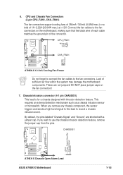
... or microswitch. By default, the pins labeled "Chassis Signal" and "Ground" are not jumpers! CPU and Chassis Fan Connectors (3-pin CPU_FAN1, CHA_FAN1) The fan connectors support cooling fans of 350mA~740mA (8.88W max.) or a total of 1A~2.22A (26.64W max.) at +12V. If you remove any chassis component, the sensor... connect the fan cables to record a chassis intrusion event. CHASSIS1 +5Volt (Power Supply Stand By) Chassis Signal Ground ® A7N8X-X 1 A7N8X-X Chassis Open Alarm Lead ASUS A7N8X-X Motherboard 1-15
... or microswitch. By default, the pins labeled "Chassis Signal" and "Ground" are not jumpers! CPU and Chassis Fan Connectors (3-pin CPU_FAN1, CHA_FAN1) The fan connectors support cooling fans of 350mA~740mA (8.88W max.) or a total of 1A~2.22A (26.64W max.) at +12V. If you remove any chassis component, the sensor... connect the fan cables to record a chassis intrusion event. CHASSIS1 +5Volt (Power Supply Stand By) Chassis Signal Ground ® A7N8X-X 1 A7N8X-X Chassis Open Alarm Lead ASUS A7N8X-X Motherboard 1-15

Motherboard DIY Troubleshooting Guide
Page 27
Power Supply Thermal Sensor (2-pin PWRTMP1) This header supports a thermal sensor for the power supply. ® A7N8X-X PWRTMP1 PWRTMP Ground A7N8X-X Power Supply Thermal Connector 13. Serial Port 2 connector (10-1 pin COM2) (optional) This ... to this connector then install the bracket into a slot opening at the back of the system chassis. ® A7N8X-X COM2 PIN 1 A7N8X-X Serial COM2 Bracket ASUS A7N8X-X Motherboard 1-17 Connect the bracket cable to receive stereo audio input from sound sources such as a CD-ROM, TV tuner, MPEG card or modem...
Power Supply Thermal Sensor (2-pin PWRTMP1) This header supports a thermal sensor for the power supply. ® A7N8X-X PWRTMP1 PWRTMP Ground A7N8X-X Power Supply Thermal Connector 13. Serial Port 2 connector (10-1 pin COM2) (optional) This ... to this connector then install the bracket into a slot opening at the back of the system chassis. ® A7N8X-X COM2 PIN 1 A7N8X-X Serial COM2 Bracket ASUS A7N8X-X Motherboard 1-17 Connect the bracket cable to receive stereo audio input from sound sources such as a CD-ROM, TV tuner, MPEG card or modem...
Motherboard DIY Troubleshooting Guide
Page 28
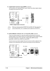
...chassis that allows digital instead of analog sound input and output. Infrared Module connector (10-1 or 10-2 pin IR_CON1) (optional) These connectors support an optional wireless transmitting and receiving infrared module. 14. GND GND ® A7N8X-X 1 SPDIF1 SPDIF_IN +5V SPDIF_OUT A7N8X-X Digital Audio ...Connector When you input sound for optional S/PDIF audio module that support this feature. You must also configure the UART2 Use As parameter in Back View and connect a ribbon cable from S/PDIF IN. 15....
...chassis that allows digital instead of analog sound input and output. Infrared Module connector (10-1 or 10-2 pin IR_CON1) (optional) These connectors support an optional wireless transmitting and receiving infrared module. 14. GND GND ® A7N8X-X 1 SPDIF1 SPDIF_IN +5V SPDIF_OUT A7N8X-X Digital Audio ...Connector When you input sound for optional S/PDIF audio module that support this feature. You must also configure the UART2 Use As parameter in Back View and connect a ribbon cable from S/PDIF IN. 15....
Motherboard DIY Troubleshooting Guide
Page 31
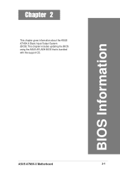
BIOS Information ASUS A7N8X-X Motherboard 2-1 Chapter 2 This chapter gives information about the ASUS A7N8X-X Basic Input/Output System (BIOS).This chapter includes updating the BIOS using the ASUS AFLASH BIOS that is bundled with the support CD.
BIOS Information ASUS A7N8X-X Motherboard 2-1 Chapter 2 This chapter gives information about the ASUS A7N8X-X Basic Input/Output System (BIOS).This chapter includes updating the BIOS using the ASUS AFLASH BIOS that is bundled with the support CD.
Motherboard DIY Troubleshooting Guide
Page 32
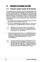
... numbers represent a newer BIOS file. 1. If you encounter problems while updating the new BIOS, DO NOT turn off the system because this happens, call the ASUS service center for example: type, "COPY A:\AWDFLASH.EXE C:\" and "COPY A:\BIOSNAME.BIN C:\. Type FORMAT A:/S at the DOS prompt to the disk. 2. Type COPY D:\SOFTWARE\AWDFLASH... the first time It is recommended that you reboot using a floppy disk in order to open DOS mode. 3. AWDFLASH works only in DOS mode. for support. 2-2 Chapter 2: BIOS Setup
... numbers represent a newer BIOS file. 1. If you encounter problems while updating the new BIOS, DO NOT turn off the system because this happens, call the ASUS service center for example: type, "COPY A:\AWDFLASH.EXE C:\" and "COPY A:\BIOSNAME.BIN C:\. Type FORMAT A:/S at the DOS prompt to the disk. 2. Type COPY D:\SOFTWARE\AWDFLASH... the first time It is recommended that you reboot using a floppy disk in order to open DOS mode. 3. AWDFLASH works only in DOS mode. for support. 2-2 Chapter 2: BIOS Setup

Motherboard DIY Troubleshooting Guide
Page 36
... two failed. When you start up the computer, the system provides you to change the configuration of the FLASH ROM. 2.2 BIOS Setup program This motherboard supports a programmable FLASH ROM that the computer can recognize these changes and record them in the CMOS RAM of your computer in section "2.1 Managing and updating...
... two failed. When you start up the computer, the system provides you to change the configuration of the FLASH ROM. 2.2 BIOS Setup program This motherboard supports a programmable FLASH ROM that the computer can recognize these changes and record them in the CMOS RAM of your computer in section "2.1 Managing and updating...
Motherboard DIY Troubleshooting Guide
Page 43
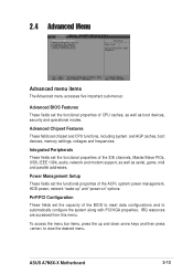
... HDD power, network "wake-up and down arrow keys and then press to automatically configure the system along with PCI/VGA properties. ASUS A7N8X-X Motherboard 2-13 IRQ resources are accessed from this menu. Power Management Setup These fields set the capacity of the BIOS to ... Chipset Features These fields set the functional properties of the IDE channels, Master/Slave PIOs, USB, IEEE 1394, audio, network and modem support, as well as boot devices, security and operational modes. Integrated Peripherals These fields set chipset and CPU functions, including system and AGP caches...
... HDD power, network "wake-up and down arrow keys and then press to automatically configure the system along with PCI/VGA properties. ASUS A7N8X-X Motherboard 2-13 IRQ resources are accessed from this menu. Power Management Setup These fields set the capacity of the BIOS to ... Chipset Features These fields set the functional properties of the IDE channels, Master/Slave PIOs, USB, IEEE 1394, audio, network and modem support, as well as boot devices, security and operational modes. Integrated Peripherals These fields set chipset and CPU functions, including system and AGP caches...


