
Motherboard DIY Troubleshooting Guide
Page 3
... ASUS contact information viii A7N8X-X specifications summary ix Chapter 1: Motherboard Info 1.1 Welcome 1-2 1.2 Package contents 1-2 1.3 Motherboard components 1-3 1.4 Motherboard layout 1-6 1.5 Before you proceed 1-7 1.6 Central Processing Unit (CPU 1-7 1.7 System memory 1-8 1.7.1 Installing a DIMM 1-8 1.8 Expansion slots 1-8 1.8.1 Configuring an expansion card 1-8 1.8.2 Standard Interrupt Assignments 1-9 1.8.3 AGP slot 1-9 1.9 Jumpers 1-10 1.10 Connectors 1-12 Chapter 2: BIOS Information 2.1 Managing and updating your BIOS...
... ASUS contact information viii A7N8X-X specifications summary ix Chapter 1: Motherboard Info 1.1 Welcome 1-2 1.2 Package contents 1-2 1.3 Motherboard components 1-3 1.4 Motherboard layout 1-6 1.5 Before you proceed 1-7 1.6 Central Processing Unit (CPU 1-7 1.7 System memory 1-8 1.7.1 Installing a DIMM 1-8 1.8 Expansion slots 1-8 1.8.1 Configuring an expansion card 1-8 1.8.2 Standard Interrupt Assignments 1-9 1.8.3 AGP slot 1-9 1.9 Jumpers 1-10 1.10 Connectors 1-12 Chapter 2: BIOS Information 2.1 Managing and updating your BIOS...
Motherboard DIY Troubleshooting Guide
Page 10
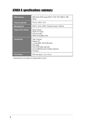
Manageability DMI 2.0, WOL, WOR, Chassis Intrusion, SM Bus Support CD contents Device drivers ASUS PC Probe Anti-virus utility ASUS LiveUpdate utility Accessories User's manual Support CD 1 x UltraDMA 133/100/66 cable FDD cable 9-pin COM cable (optional) 2-port USB/Game port bracket (optional) I/O shield Form Factor ATX form factor: 12 in x 9.6 in * Specifications are subject to change without notice. x A7N8X-X specifications summary BIOS features 2Mb Flash ROM, Award BIOS, TCAV, PnP, DMI2.0, DMI, Green Industry standard PCI 2.2, USB 1.1/2.0.
Manageability DMI 2.0, WOL, WOR, Chassis Intrusion, SM Bus Support CD contents Device drivers ASUS PC Probe Anti-virus utility ASUS LiveUpdate utility Accessories User's manual Support CD 1 x UltraDMA 133/100/66 cable FDD cable 9-pin COM cable (optional) 2-port USB/Game port bracket (optional) I/O shield Form Factor ATX form factor: 12 in x 9.6 in * Specifications are subject to change without notice. x A7N8X-X specifications summary BIOS features 2Mb Flash ROM, Award BIOS, TCAV, PnP, DMI2.0, DMI, Green Industry standard PCI 2.2, USB 1.1/2.0.
Motherboard DIY Troubleshooting Guide
Page 14
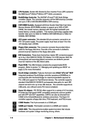
..., USB and support for 333MHz DDR SDRAM. 4 ATX power connector. This standard 20-pin connector connects to a GAME port module. 12 ASUS ASIC. These dual-channel bus master IDE connectors support up to 3 GB of the IDE ribbon cable. 7 Flash ROM. Both the primary...8482; 400 North Bridge controller chipset. One side of the connector is PCI rev2.2 compliant. 9 Super I/O chipset. This 2Mb firmware contains the programmable BIOS program. (Refer to prevent incorrect insertion of I /O controller supports a floppy disk drive, PS/2 keyboard, and PS/2 mouse. 10 COM2 Header. ...
..., USB and support for 333MHz DDR SDRAM. 4 ATX power connector. This standard 20-pin connector connects to a GAME port module. 12 ASUS ASIC. These dual-channel bus master IDE connectors support up to 3 GB of the IDE ribbon cable. 7 Flash ROM. Both the primary...8482; 400 North Bridge controller chipset. One side of the connector is PCI rev2.2 compliant. 9 Super I/O chipset. This 2Mb firmware contains the programmable BIOS program. (Refer to prevent incorrect insertion of I /O controller supports a floppy disk drive, PS/2 keyboard, and PS/2 mouse. 10 COM2 Header. ...
Motherboard DIY Troubleshooting Guide
Page 16
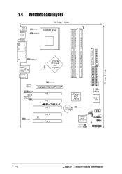
... FPAUDIO1 AUX1 Audio Codec SPDIF1 Accelerated Graphics Port (AGP) PCI 1 PCI 2 ®A7N8X-X PCI 3 nForce2 MCP Chipset CR2032 3V Lithium Cell CMOS Power CLRTC1 2Mb BIOS Super I/O USB56 COM2 MODEM1 PWR_LED1 PCI 4 PCI 5 USBPWR_56 ASUS ASIC with Hardware Monitor GAME1 IR_CON1 IDELED1 PWRTMP1 CHASSIS1 CTRL_PANEL1 1-6 Chapter 1: Motherboard Information
... FPAUDIO1 AUX1 Audio Codec SPDIF1 Accelerated Graphics Port (AGP) PCI 1 PCI 2 ®A7N8X-X PCI 3 nForce2 MCP Chipset CR2032 3V Lithium Cell CMOS Power CLRTC1 2Mb BIOS Super I/O USB56 COM2 MODEM1 PWR_LED1 PCI 4 PCI 5 USBPWR_56 ASUS ASIC with Hardware Monitor GAME1 IR_CON1 IDELED1 PWRTMP1 CHASSIS1 CTRL_PANEL1 1-6 Chapter 1: Motherboard Information
Motherboard DIY Troubleshooting Guide
Page 18
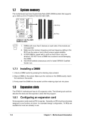
... notches in the socket. 3. Generally, an IRQ must be exclusively assigned to one direction. Make sure the memory frequency and bus frequency setting in the BIOS are already in use. 1-8 Chapter 1: Motherboard Information Unlock a DIMM socket by pressing the retaining clips outward. 2. 1.7 System memory The motherboard has three Double Data ...2100/1600 DDR.. 104 Pins ® A7N8X-X 80 Pins A7N8X-X 184-Pin DDR DIMM Sockets 1. DIMMs with a notch so that supports up to operate. Visit ASUS website (www.asus.com) for latest DDR400 Qualified Vendor List. 1.7.1 Installing a DIMM 1.
... notches in the socket. 3. Generally, an IRQ must be exclusively assigned to one direction. Make sure the memory frequency and bus frequency setting in the BIOS are already in use. 1-8 Chapter 1: Motherboard Information Unlock a DIMM socket by pressing the retaining clips outward. 2. 1.7 System memory The motherboard has three Double Data ...2100/1600 DDR.. 104 Pins ® A7N8X-X 80 Pins A7N8X-X 184-Pin DDR DIMM Sockets 1. DIMMs with a notch so that supports up to operate. Visit ASUS website (www.asus.com) for latest DDR400 Qualified Vendor List. 1.7.1 Installing a DIMM 1.
Motherboard DIY Troubleshooting Guide
Page 19
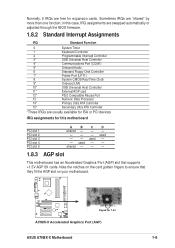
...devices. used - - used - - IRQ assignments for expansion cards. Normally, 6 IRQs are free for this case, IRQ assignments are swapped automatically or adjusted through the BIOS firmware. 1.8.2 Standard Interrupt Assignments IRQ Standard Function 0 System Timer 1 Keyboard Controller 2 Programmable Interrupt Controller 3* USB Universal Host Controller 4* Communications Port (COM1) 5* Onboard ... Ultra ATA Controller 15* Secondary Ultra ATA Controller *These IRQs are usually available for 1.5v A7N8X-X Accelerated Graphics Port (AGP) ASUS A7N8X-X Motherboard 1-9
...devices. used - - used - - IRQ assignments for expansion cards. Normally, 6 IRQs are free for this case, IRQ assignments are swapped automatically or adjusted through the BIOS firmware. 1.8.2 Standard Interrupt Assignments IRQ Standard Function 0 System Timer 1 Keyboard Controller 2 Programmable Interrupt Controller 3* USB Universal Host Controller 4* Communications Port (COM1) 5* Onboard ... Ultra ATA Controller 15* Secondary Ultra ATA Controller *These IRQs are usually available for 1.5v A7N8X-X Accelerated Graphics Port (AGP) ASUS A7N8X-X Motherboard 1-9

Motherboard DIY Troubleshooting Guide
Page 21
...the Real Time Clock (RTC) RAM of date, time and system setup parameters in the BIOS (see section 2.5.1 Power Up Control). ® A7N8X-X KBPWR1 12 +5V (Default) 23 +5VSB A7N8X-X Keyboard Power Setting ASUS A7N8X-X Motherboard 1-11 Plug the power cord and turn ON the computer. 6. Set ... by the onboard button cell battery. Turn OFF the computer and unplug the power cord. 2. Hold down the key during the boot process and enter BIOS setup to the original position, [1-2]. 4. 3. Re-install the battery. 5. The RAM data in CMOS is [Disabled]). Remove the battery. 3. Keyboard power...
...the Real Time Clock (RTC) RAM of date, time and system setup parameters in the BIOS (see section 2.5.1 Power Up Control). ® A7N8X-X KBPWR1 12 +5V (Default) 23 +5VSB A7N8X-X Keyboard Power Setting ASUS A7N8X-X Motherboard 1-11 Plug the power cord and turn ON the computer. 6. Set ... by the onboard button cell battery. Turn OFF the computer and unplug the power cord. 2. Hold down the key during the boot process and enter BIOS setup to the original position, [1-2]. 4. 3. Re-install the battery. 5. The RAM data in CMOS is [Disabled]). Remove the battery. 3. Keyboard power...
Motherboard DIY Troubleshooting Guide
Page 22
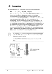
... connector supports the provided UltraDMA/133/100/66 IDE hard disk ribbon cable. 1.10 Connectors This section describes and illustrates the connectors on the motherboard. 1. BIOS supports specific device bootup. It is removed to match the covered hole on the IDE ribbon cable to the secondary IDE connector.
... connector supports the provided UltraDMA/133/100/66 IDE hard disk ribbon cable. 1.10 Connectors This section describes and illustrates the connectors on the motherboard. 1. BIOS supports specific device bootup. It is removed to match the covered hole on the IDE ribbon cable to the secondary IDE connector.
Motherboard DIY Troubleshooting Guide
Page 28
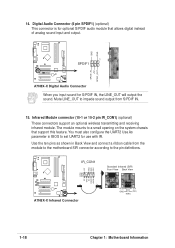
... also configure the UART2 Use As parameter in Back View and connect a ribbon cable from S/PDIF IN. 15. Use the ten pins as shown in BIOS to the pin definitions. ® A7N8X-X NC GND NC CIRRX +5VSB +5 V IRRX GND IRTX IR_CON1 SIR CIR A7N8X-X Infrared Connector Standard Infrared (SIR) Front View...
... also configure the UART2 Use As parameter in Back View and connect a ribbon cable from S/PDIF IN. 15. Use the ten pins as shown in BIOS to the pin definitions. ® A7N8X-X NC GND NC CIRRX +5VSB +5 V IRRX GND IRTX IR_CON1 SIR CIR A7N8X-X Infrared Connector Standard Infrared (SIR) Front View...

Motherboard DIY Troubleshooting Guide
Page 29
... Ground Ground Speaker ExtSMI# Ground PWR GND Reset Ground ® A7N8X-X Reset SW SMI Lead ATX Power Switch* * Requires an ATX power supply. ASUS A7N8X-X Motherboard 1-19 The LED lights up when you to hear system beeps and warnings. • System Management Interrupt Lead (2-pin SMI) This 2-...pin connector permits switching to the case-mounted speaker and allows you turn on the BIOS or OS settings. Pressing the power switch turns the system between ON and SLEEP, or ON and SOFT OFF, depending on the system power....
... Ground Ground Speaker ExtSMI# Ground PWR GND Reset Ground ® A7N8X-X Reset SW SMI Lead ATX Power Switch* * Requires an ATX power supply. ASUS A7N8X-X Motherboard 1-19 The LED lights up when you to hear system beeps and warnings. • System Management Interrupt Lead (2-pin SMI) This 2-...pin connector permits switching to the case-mounted speaker and allows you turn on the BIOS or OS settings. Pressing the power switch turns the system between ON and SLEEP, or ON and SOFT OFF, depending on the system power....
Motherboard DIY Troubleshooting Guide
Page 31
Chapter 2 This chapter gives information about the ASUS A7N8X-X Basic Input/Output System (BIOS).This chapter includes updating the BIOS using the ASUS AFLASH BIOS that is bundled with the support CD. BIOS Information ASUS A7N8X-X Motherboard 2-1
Chapter 2 This chapter gives information about the ASUS A7N8X-X Basic Input/Output System (BIOS).This chapter includes updating the BIOS using the ASUS AFLASH BIOS that is bundled with the support CD. BIOS Information ASUS A7N8X-X Motherboard 2-1
Motherboard DIY Troubleshooting Guide
Page 32
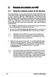
... to clear the CMOS memory (see section 1.7, Jumpers). If you encounter problems while updating the new BIOS, DO NOT turn off the system because this happens, call the ASUS service center for example: type, "COPY A:\AWDFLASH.EXE C:\" and "COPY A:\BIOSNAME.BIN C:\. DO NOT copy AUTOEXEC.BAT and... CONFIG.SYS to create a bootable system disk. If the Flash Memory Writer utility is not able to successfully update a complete BIOS file, the system...
... to clear the CMOS memory (see section 1.7, Jumpers). If you encounter problems while updating the new BIOS, DO NOT turn off the system because this happens, call the ASUS service center for example: type, "COPY A:\AWDFLASH.EXE C:\" and "COPY A:\BIOSNAME.BIN C:\. DO NOT copy AUTOEXEC.BAT and... CONFIG.SYS to create a bootable system disk. If the Flash Memory Writer utility is not able to successfully update a complete BIOS file, the system...
Motherboard DIY Troubleshooting Guide
Page 33
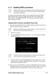
...or using a bootable floppy disk with the motherboard and you see ASUS contact info on Page viii). Select since it . ASUS A7N8X-X Motherboard 2-3 what you are sure that contains the new BIOS file into the floppy drive. The BIOS information in the above screen is advisable to type the exact... BIOS file name at the Award BIOS Flash Utility. 2. if you want to a floppy disk. Updating BIOS via Built-in the drive. 5. Download the latest BIOS file from the ASUS website (see on a piece of the new BIOS file, for reference only. Type the ...
...or using a bootable floppy disk with the motherboard and you see ASUS contact info on Page viii). Select since it . ASUS A7N8X-X Motherboard 2-3 what you are sure that contains the new BIOS file into the floppy drive. The BIOS information in the above screen is advisable to type the exact... BIOS file name at the Award BIOS Flash Utility. 2. if you want to a floppy disk. Updating BIOS via Built-in the drive. 5. Download the latest BIOS file from the ASUS website (see on a piece of the new BIOS file, for reference only. Type the ...

Motherboard DIY Troubleshooting Guide
Page 34
The AWDFLASH program backsup the file. 7. AWDFLASH proceeds to check the new BIOS file and asks the user to program (flash) the new BIOS file to a separate file. The program asks to save the previous BIOS to the motherboard. 8. Type and Press to flash the new Bios file. NOTE: Do not shut off system power or unplug the supply during the flash process. 2-4 Chapter 2: BIOS Setup Type a file name for the old bios and then press . 6.
The AWDFLASH program backsup the file. 7. AWDFLASH proceeds to check the new BIOS file and asks the user to program (flash) the new BIOS file to a separate file. The program asks to save the previous BIOS to the motherboard. 8. Type and Press to flash the new Bios file. NOTE: Do not shut off system power or unplug the supply during the flash process. 2-4 Chapter 2: BIOS Setup Type a file name for the old bios and then press . 6.
Motherboard DIY Troubleshooting Guide
Page 35
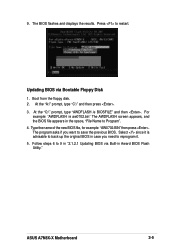
... to reprogram it. 5. Follow steps 6 to Program". 4. At the "C:\" prompt, type "AWDFLASH /e BIOSFILE" and then . ASUS A7N8X-X Motherboard 2-5 The BIOS flashes and displays the results. Updating BIOS via Built-in the space, "File Name to 9 in "2.1.2.1 Updating BIOS via Bootable Floppy Disk 1. At the "A:\" prompt, type "C:\" and then press . 3. Type the name of the...
... to reprogram it. 5. Follow steps 6 to Program". 4. At the "C:\" prompt, type "AWDFLASH /e BIOSFILE" and then . ASUS A7N8X-X Motherboard 2-5 The BIOS flashes and displays the results. Updating BIOS via Built-in the space, "File Name to 9 in "2.1.2.1 Updating BIOS via Bootable Floppy Disk 1. At the "A:\" prompt, type "C:\" and then press . 3. Type the name of the...

Motherboard DIY Troubleshooting Guide
Page 36
...when you can update using this program. You can also restart by pressing the reset button on the motherboard stores the Setup utility. Because the BIOS software is a menudriven program, which means you wish to "Run Setup". Press during the Power-On Self Test (POST) to enter the ...and may not exactly match what you with its test routines. When you start up the computer, the system provides you see on . 2.2 BIOS Setup program This motherboard supports a programmable FLASH ROM that the computer can recognize these changes and record them in the future. If you can ...
...when you can update using this program. You can also restart by pressing the reset button on the motherboard stores the Setup utility. Because the BIOS software is a menudriven program, which means you wish to "Run Setup". Press during the Power-On Self Test (POST) to enter the ...and may not exactly match what you with its test routines. When you start up the computer, the system provides you see on . 2.2 BIOS Setup program This motherboard supports a programmable FLASH ROM that the computer can recognize these changes and record them in the future. If you can ...
Motherboard DIY Troubleshooting Guide
Page 37
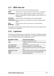
... values for the highlighted field Brings up or down between fields Scrolls backward through the values for the highlighted field Saves changes and Exit ASUS A7N8X-X Motherboard 2-7 The keys in the legend bar with the following selections: MAIN Use this menu to enable and make changes to... and PnP/ PCI configurations. The following table lists the keys found in the legend bar allow you to exit the Setup MONITOR program. 2.2.1 BIOS menu bar The top of the screen has a menu bar with their corresponding functions. ADVANCED Use this menu to make changes to the basic...
... values for the highlighted field Brings up or down between fields Scrolls backward through the values for the highlighted field Saves changes and Exit ASUS A7N8X-X Motherboard 2-7 The keys in the legend bar with the following selections: MAIN Use this menu to enable and make changes to... and PnP/ PCI configurations. The following table lists the keys found in the legend bar allow you to exit the Setup MONITOR program. 2.2.1 BIOS menu bar The top of the screen has a menu bar with their corresponding functions. ADVANCED Use this menu to make changes to the basic...

Motherboard DIY Troubleshooting Guide
Page 38
To exit the help text for the currently highlighted field. 2-8 Chapter 2: BIOS Setup Saving changes and exiting the Setup program See "4.7 Exit Menu" for a field parameter. Scroll bar When a scroll bar appears to the right of each ... Item Specific Help window located to the right of a help window, it indicates that there is more information to the Item Specific Help window, the BIOS setup program also provides a General Help screen. This pointer indicates that a right pointer symbol (as you can display a sub-menu from this screen from any...
To exit the help text for the currently highlighted field. 2-8 Chapter 2: BIOS Setup Saving changes and exiting the Setup program See "4.7 Exit Menu" for a field parameter. Scroll bar When a scroll bar appears to the right of each ... Item Specific Help window located to the right of a help window, it indicates that there is more information to the Item Specific Help window, the BIOS setup program also provides a General Help screen. This pointer indicates that a right pointer symbol (as you can display a sub-menu from this screen from any...

Motherboard DIY Troubleshooting Guide
Page 40
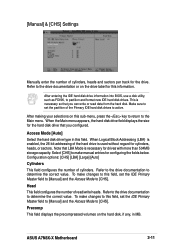
... in the correct values for more details. If automatic detection fails, this may be because the hard disk drive is successful, the setup BIOS automatically fills in order to enter the Hard Disk Drive values manually. If no drive is not already detected. Before attempting to configure a...Access Mode below and refer to the next page for the remaining fields on a previous system, the setup BIOS may cause the system to fail to recognize the installed hard disk. 2-10 Chapter 2: BIOS Setup Configuration options: [None] [Auto [Manual] Access Mode [Auto] The default [Auto] automatically detects...
... in the correct values for more details. If automatic detection fails, this may be because the hard disk drive is successful, the setup BIOS automatically fills in order to enter the Hard Disk Drive values manually. If no drive is not already detected. Before attempting to configure a...Access Mode below and refer to the next page for the remaining fields on a previous system, the setup BIOS may cause the system to fail to recognize the installed hard disk. 2-10 Chapter 2: BIOS Setup Configuration options: [None] [Auto [Manual] Access Mode [Auto] The default [Auto] automatically detects...
Motherboard DIY Troubleshooting Guide
Page 41
... menu appears, the hard disk drive field displays the size for configuring the fields below. Precomp This field displays the precompressed volumes on this field. ASUS A7N8X-X Motherboard 2-11 Configuration options: [CHS] [LBA] [Large] [Auto] Cylinders This field configures the number of read data from the hard ... the number of cylinders, heads and sectors per track for cylinders, heads, or sectors. After entering the IDE hard disk drive information into BIOS, use a disk utility, such as FDISK, to make changes to this field, set the partition of the Primary IDE hard disk drives ...
... menu appears, the hard disk drive field displays the size for configuring the fields below. Precomp This field displays the precompressed volumes on this field. ASUS A7N8X-X Motherboard 2-11 Configuration options: [CHS] [LBA] [Large] [Auto] Cylinders This field configures the number of read data from the hard ... the number of cylinders, heads and sectors per track for cylinders, heads, or sectors. After entering the IDE hard disk drive information into BIOS, use a disk utility, such as FDISK, to make changes to this field, set the partition of the Primary IDE hard disk drives ...


