
Motherboard DIY Troubleshooting Guide
Page 21
... jumper to pins 2-3 (+5VSB) if you wish to wake up feature. Re-install the battery. 5. To erase the RTC RAM: 1. Replace the jumper cap to enable or disable the keyboard wake-up the computer when you to the original position, [1-2]. 4. This feature requires an ...computer and unplug the power cord. 2. The RAM data in the BIOS (see section 2.5.1 Power Up Control). ® A7N8X-X KBPWR1 12 +5V (Default) 23 +5VSB A7N8X-X Keyboard Power Setting ASUS A7N8X-X Motherboard 1-11 Remove the battery. 3. 3. Clear RTC RAM (CLRTC1) (optional) This jumper clears the Real Time Clock ...
... jumper to pins 2-3 (+5VSB) if you wish to wake up feature. Re-install the battery. 5. To erase the RTC RAM: 1. Replace the jumper cap to enable or disable the keyboard wake-up the computer when you to the original position, [1-2]. 4. This feature requires an ...computer and unplug the power cord. 2. The RAM data in the BIOS (see section 2.5.1 Power Up Control). ® A7N8X-X KBPWR1 12 +5V (Default) 23 +5VSB A7N8X-X Keyboard Power Setting ASUS A7N8X-X Motherboard 1-11 Remove the battery. 3. 3. Clear RTC RAM (CLRTC1) (optional) This jumper clears the Real Time Clock ...
Motherboard DIY Troubleshooting Guide
Page 23
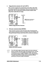
...3. Floppy disk drive connector (34-1 pin FLOPPY1) This connector supports the provided floppy drive ribbon cable. The minimum recommended wattage is inadequate. ASUS A7N8X-X Motherboard 1-13 Find the proper orientation and push down firmly until the connectors completely fit. After connecting one orientation. The system may become unstable...fit these connectors in only one end to the motherboard, connect the other end to the floppy drive. (Pin 5 is removed to replace the power supply in the future, make sure that your new ATX 12V power supply can provide 8A on the +12V lead and at...
...3. Floppy disk drive connector (34-1 pin FLOPPY1) This connector supports the provided floppy drive ribbon cable. The minimum recommended wattage is inadequate. ASUS A7N8X-X Motherboard 1-13 Find the proper orientation and push down firmly until the connectors completely fit. After connecting one orientation. The system may become unstable...fit these connectors in only one end to the motherboard, connect the other end to the floppy drive. (Pin 5 is removed to replace the power supply in the future, make sure that your new ATX 12V power supply can provide 8A on the +12V lead and at...
A7N8X-X User's Manual
Page 21
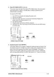
...[1-2] to the original position, [1-2]. 4. Plug the power cord and turn ON the computer. 6. Replace the jumper cap to [2-3] momentarily. CLRTC1 1 2 ® 2 3 Clear CMOS A7N8X-X Normal (Default) A7N8X-X Clear RTC RAM 4. 3. This feature requires an ATX power supply that can supply at least ...a key on the +5VSB lead, and a corresponding setting in CMOS. KBPWR1 1 2 +5V (Default) ® 2 3 +5VSB A7N8X-X A7N8X-X Keyboard Power Setting ASUS A7N8X-X Motherboard 1-11 Re-install the battery. 5. To erase the RTC RAM: 1. Hold down the key during the boot process and enter ...
...[1-2] to the original position, [1-2]. 4. Plug the power cord and turn ON the computer. 6. Replace the jumper cap to [2-3] momentarily. CLRTC1 1 2 ® 2 3 Clear CMOS A7N8X-X Normal (Default) A7N8X-X Clear RTC RAM 4. 3. This feature requires an ATX power supply that can supply at least ...a key on the +5VSB lead, and a corresponding setting in CMOS. KBPWR1 1 2 +5V (Default) ® 2 3 +5VSB A7N8X-X A7N8X-X Keyboard Power Setting ASUS A7N8X-X Motherboard 1-11 Re-install the battery. 5. To erase the RTC RAM: 1. Hold down the key during the boot process and enter ...

A7N8X-X User's Manual
Page 23
...sure that your new ATX 12V power supply can provide 8A on the +12V lead and at least 1A on the floppy ribbon cable to replace the power supply in only one end to the motherboard, connect the other end to the floppy drive. (Pin 5 is removed to an... power supply. The system may become unstable and may experience difficulty powering up if the power supply is 230W, or 300W for a fully configured system. ASUS A7N8X-X Motherboard 1-13 2. Floppy disk drive connector (34-1 pin FLOPPY1) This connector supports the provided floppy drive ribbon cable. ATXPWR1 +3.3VDC -12.0VDC COM...
...sure that your new ATX 12V power supply can provide 8A on the +12V lead and at least 1A on the floppy ribbon cable to replace the power supply in only one end to the motherboard, connect the other end to the floppy drive. (Pin 5 is removed to an... power supply. The system may become unstable and may experience difficulty powering up if the power supply is 230W, or 300W for a fully configured system. ASUS A7N8X-X Motherboard 1-13 2. Floppy disk drive connector (34-1 pin FLOPPY1) This connector supports the provided floppy drive ribbon cable. ATXPWR1 +3.3VDC -12.0VDC COM...


