Motherboard DIY Troubleshooting Guide
Page 17
...A7N8X-X CPU NOTCH TO INNER CORNER AMD™ CPU LOCK LEVER CPU NOTCH A7N8X-X Socket 462 Each AMD CPU has a "marked" corner. 1.5 Before you proceed Take note of less than 1GHz on a grounded antistatic pad or in the bag that the ATX power supply... is switched off or the power... as the power supply case, before...) for CPU installation. The A7N8X-X supports Athlon™ XP processors...the power cord from the power supply....
...A7N8X-X CPU NOTCH TO INNER CORNER AMD™ CPU LOCK LEVER CPU NOTCH A7N8X-X Socket 462 Each AMD CPU has a "marked" corner. 1.5 Before you proceed Take note of less than 1GHz on a grounded antistatic pad or in the bag that the ATX power supply... is switched off or the power... as the power supply case, before...) for CPU installation. The A7N8X-X supports Athlon™ XP processors...the power cord from the power supply....
Motherboard DIY Troubleshooting Guide
Page 20
...) 2 3 FSB200 1-10 A7N8X-X CPU FSB Jumper Setting Chapter 1: Motherboard Information 1.9 Jumpers This section describes and illustrates the jumpers on the +5VSB lead when these jumpers to +5V to wake up the computer from S3 sleep mode (no power to CPU, DRAM in slow refresh, power supply in reduced power mode). This feature requires a power supply that you...
...) 2 3 FSB200 1-10 A7N8X-X CPU FSB Jumper Setting Chapter 1: Motherboard Information 1.9 Jumpers This section describes and illustrates the jumpers on the +5VSB lead when these jumpers to +5V to wake up the computer from S3 sleep mode (no power to CPU, DRAM in slow refresh, power supply in reduced power mode). This feature requires a power supply that you...

Motherboard DIY Troubleshooting Guide
Page 21
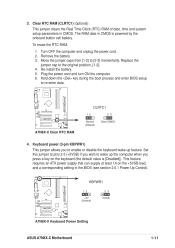
...enter data. ® A7N8X-X A7N8X-X Clear RTC RAM CLRTC1 12 23 Normal (Default) Clear CMOS 4. Turn OFF the computer and unplug the power cord. 2. This feature requires an ATX power supply that can supply at least 1A on the keyboard (the default value is powered by the onboard button ... pins 2-3 (+5VSB) if you press a key on the +5VSB lead, and a corresponding setting in the BIOS (see section 2.5.1 Power Up Control). ® A7N8X-X KBPWR1 12 +5V (Default) 23 +5VSB A7N8X-X Keyboard Power Setting ASUS A7N8X-X Motherboard 1-11 Set this jumper to [2-3] momentarily.
...enter data. ® A7N8X-X A7N8X-X Clear RTC RAM CLRTC1 12 23 Normal (Default) Clear CMOS 4. Turn OFF the computer and unplug the power cord. 2. This feature requires an ATX power supply that can supply at least 1A on the keyboard (the default value is powered by the onboard button ... pins 2-3 (+5VSB) if you press a key on the +5VSB lead, and a corresponding setting in the BIOS (see section 2.5.1 Power Up Control). ® A7N8X-X KBPWR1 12 +5V (Default) 23 +5VSB A7N8X-X Keyboard Power Setting ASUS A7N8X-X Motherboard 1-11 Set this jumper to [2-3] momentarily.
Motherboard DIY Troubleshooting Guide
Page 23
... is inadequate. The system may become unstable and may experience difficulty powering up if the power supply is 230W, or 300W for a fully configured system. Find the proper orientation and push down firmly until the connectors completely fit. ASUS A7N8X-X Motherboard 1-13 ATXPWR1 ® A7N8X-X +3.3VDC -12.0VDC COM PS_ON# COM COM COM -5.0VDC +5.0VDC +5.0VDC...
... is inadequate. The system may become unstable and may experience difficulty powering up if the power supply is 230W, or 300W for a fully configured system. Find the proper orientation and push down firmly until the connectors completely fit. ASUS A7N8X-X Motherboard 1-13 ATXPWR1 ® A7N8X-X +3.3VDC -12.0VDC COM PS_ON# COM COM COM -5.0VDC +5.0VDC +5.0VDC...
Motherboard DIY Troubleshooting Guide
Page 25
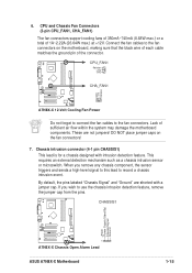
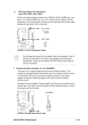
... intrusion detection feature, remove the jumper cap from the pins. CHASSIS1 +5Volt (Power Supply Stand By) Chassis Signal Ground ® A7N8X-X 1 A7N8X-X Chassis Open Alarm Lead ASUS A7N8X-X Motherboard 1-15 CPU_FAN1 Rotation +12V GND ® A7N8X-X CHA_FAN1 GND +12V Rotation A7N8X-X 12-Volt Cooling Fan Power Do not forget to connect the fan cables to the fan connectors on...
... intrusion detection feature, remove the jumper cap from the pins. CHASSIS1 +5Volt (Power Supply Stand By) Chassis Signal Ground ® A7N8X-X 1 A7N8X-X Chassis Open Alarm Lead ASUS A7N8X-X Motherboard 1-15 CPU_FAN1 Rotation +12V GND ® A7N8X-X CHA_FAN1 GND +12V Rotation A7N8X-X 12-Volt Cooling Fan Power Do not forget to connect the fan cables to the fan connectors on...

Motherboard DIY Troubleshooting Guide
Page 27
...then install the bracket into a slot opening at the back of the system chassis. ® A7N8X-X COM2 PIN 1 A7N8X-X Serial COM2 Bracket ASUS A7N8X-X Motherboard 1-17 MODEM1 CD1 (Black) AUX1 (White) ® A7N8X-X A7N8X-X Internal Audio Connectors 12. Serial Port 2 connector (10-1 pin COM2) (optional) This connector... audio input from sound sources such as a CD-ROM, TV tuner, MPEG card or modem. Power Supply Thermal Sensor (2-pin PWRTMP1) This header supports a thermal sensor for the power supply. ® A7N8X-X PWRTMP1 PWRTMP Ground A7N8X-X Power Supply Thermal Connector 13.
...then install the bracket into a slot opening at the back of the system chassis. ® A7N8X-X COM2 PIN 1 A7N8X-X Serial COM2 Bracket ASUS A7N8X-X Motherboard 1-17 MODEM1 CD1 (Black) AUX1 (White) ® A7N8X-X A7N8X-X Internal Audio Connectors 12. Serial Port 2 connector (10-1 pin COM2) (optional) This connector... audio input from sound sources such as a CD-ROM, TV tuner, MPEG card or modem. Power Supply Thermal Sensor (2-pin PWRTMP1) This header supports a thermal sensor for the power supply. ® A7N8X-X PWRTMP1 PWRTMP Ground A7N8X-X Power Supply Thermal Connector 13.

Motherboard DIY Troubleshooting Guide
Page 29
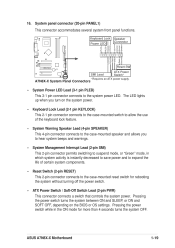
... for rebooting the system without turning off the power switch. • ATX Power Switch / Soft-Off Switch Lead (2-pin PWR) This connector connects a switch that controls the system power. A7N8X-X System Panel Connectors • System Power LED Lead (3-1 pin PLED) This 3-1 pin... 2-pin connector connects to the system power LED. Keyboard Lock Speaker Power LED Connector PLED+ PLEDKeylock Ground +5V Ground Ground Speaker ExtSMI# Ground PWR GND Reset Ground ® A7N8X-X Reset SW SMI Lead ATX Power Switch* * Requires an ATX power supply. ASUS A7N8X-X Motherboard 1-19 16.
... for rebooting the system without turning off the power switch. • ATX Power Switch / Soft-Off Switch Lead (2-pin PWR) This connector connects a switch that controls the system power. A7N8X-X System Panel Connectors • System Power LED Lead (3-1 pin PLED) This 3-1 pin... 2-pin connector connects to the system power LED. Keyboard Lock Speaker Power LED Connector PLED+ PLEDKeylock Ground +5V Ground Ground Speaker ExtSMI# Ground PWR GND Reset Ground ® A7N8X-X Reset SW SMI Lead ATX Power Switch* * Requires an ATX power supply. ASUS A7N8X-X Motherboard 1-19 16.

A7N8X-X User's Manual
Page 17
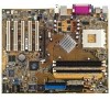
...the ATX power supply is switched off or the power cord is usually indicated with the component. 5. AMD processors offer gigahertz speeds to the motherboard, peripherals, and/or components. CPU NOTCH TO INNER CORNER LOCK LEVER ® A7N8X-X AMD™ CPU CPU NOTCH A7N8X-X Socket ... any component. 2. Use a grounded wrist strap or touch a safely grounded object or to static electricity. 3. Unplug the power cord from the power supply. The A7N8X-X supports Athlon™ XP processors with core speeds of the following precautions before handling components to this motherboard...
...the ATX power supply is switched off or the power cord is usually indicated with the component. 5. AMD processors offer gigahertz speeds to the motherboard, peripherals, and/or components. CPU NOTCH TO INNER CORNER LOCK LEVER ® A7N8X-X AMD™ CPU CPU NOTCH A7N8X-X Socket ... any component. 2. Use a grounded wrist strap or touch a safely grounded object or to static electricity. 3. Unplug the power cord from the power supply. The A7N8X-X supports Athlon™ XP processors with core speeds of the following precautions before handling components to this motherboard...

A7N8X-X User's Manual
Page 20
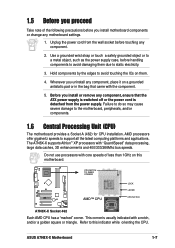
...2 3 FSB200 A7N8X-X FSB400/333/266 (Default) A7N8X-X CPU FSB Jumper Setting 1-10 Chapter 1: Motherboard Information The USBPWR_12 and USBPWR_34 jumpers are for the internal USB header that can connect to wake up from S1 sleep mode (CPU stopped, DRAM refreshed, system running in low power mode) using ...Central Processing Unit FSB (CPU_FSB) This jumper when set to pins 1-2 (+5V) by default because not all computers have the appropriate power supply to 1-2 pins (default), enable support for FSB 200 only. Jumpers USB device wake-up (3-pin USBPWR_12,USBPWR_34,USBPWR_56) Set these jumpers...
...2 3 FSB200 A7N8X-X FSB400/333/266 (Default) A7N8X-X CPU FSB Jumper Setting 1-10 Chapter 1: Motherboard Information The USBPWR_12 and USBPWR_34 jumpers are for the internal USB header that can connect to wake up from S1 sleep mode (CPU stopped, DRAM refreshed, system running in low power mode) using ...Central Processing Unit FSB (CPU_FSB) This jumper when set to pins 1-2 (+5V) by default because not all computers have the appropriate power supply to 1-2 pins (default), enable support for FSB 200 only. Jumpers USB device wake-up (3-pin USBPWR_12,USBPWR_34,USBPWR_56) Set these jumpers...
A7N8X-X User's Manual
Page 21
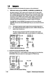
... in CMOS. To erase the RTC RAM: 1. KBPWR1 1 2 +5V (Default) ® 2 3 +5VSB A7N8X-X A7N8X-X Keyboard Power Setting ASUS A7N8X-X Motherboard 1-11 Plug the power cord and turn ON the computer. 6. CLRTC1 1 2 ® 2 3 Clear CMOS A7N8X-X Normal (Default) A7N8X-X Clear RTC RAM 4. This feature requires an ATX power supply that can supply at least 1A on the keyboard (the default value is...
... in CMOS. To erase the RTC RAM: 1. KBPWR1 1 2 +5V (Default) ® 2 3 +5VSB A7N8X-X A7N8X-X Keyboard Power Setting ASUS A7N8X-X Motherboard 1-11 Plug the power cord and turn ON the computer. 6. CLRTC1 1 2 ® 2 3 Clear CMOS A7N8X-X Normal (Default) A7N8X-X Clear RTC RAM 4. This feature requires an ATX power supply that can supply at least 1A on the keyboard (the default value is...

A7N8X-X User's Manual
Page 23
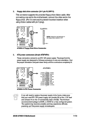
...12.0VDC ® A7N8X-X A7N8X-X ATX Power Connector If you will need to an ATX 12V power supply. ASUS A7N8X-X Motherboard 1-13 ATX power connectors (20-pin ATXPWR1) These connectors connect to replace the power supply in the future, make sure that your new ATX 12V power supply can provide 8A on... FLOPPY1 NOTE: Orient the red markings on the +5-volt standby lead (+5VSB). The plugs from the power supply are designed to PIN 1 ® A7N8X-X PIN 1 A7N8X-X Floppy Disk Drive Connector 3. 2. After connecting one orientation. The minimum recommended wattage is removed to ...
...12.0VDC ® A7N8X-X A7N8X-X ATX Power Connector If you will need to an ATX 12V power supply. ASUS A7N8X-X Motherboard 1-13 ATX power connectors (20-pin ATXPWR1) These connectors connect to replace the power supply in the future, make sure that your new ATX 12V power supply can provide 8A on... FLOPPY1 NOTE: Orient the red markings on the +5-volt standby lead (+5VSB). The plugs from the power supply are designed to PIN 1 ® A7N8X-X PIN 1 A7N8X-X Floppy Disk Drive Connector 3. 2. After connecting one orientation. The minimum recommended wattage is removed to ...
A7N8X-X User's Manual
Page 25
... This lead is for a chassis designed with a jumper cap. Lack of the connector. CHASSIS1 +5Volt (Power Supply Stand By) Chassis Signal Ground 1 ® A7N8X-X A7N8X-X Chassis Open Alarm Lead ASUS A7N8X-X Motherboard GND +12V Rotation 1-15 If you remove any chassis component, the sensor triggers and sends a ...or a total of 1A~2.22A (26.64W max.) at +12V. 6. CPU_FAN1 Rotation +12V GND CHA_FAN1 ® A7N8X-X A7N8X-X 12-Volt Cooling Fan Power Do not forget to connect the fan cables to record a chassis intrusion event. These are shorted with intrusion detection feature.
... This lead is for a chassis designed with a jumper cap. Lack of the connector. CHASSIS1 +5Volt (Power Supply Stand By) Chassis Signal Ground 1 ® A7N8X-X A7N8X-X Chassis Open Alarm Lead ASUS A7N8X-X Motherboard GND +12V Rotation 1-15 If you remove any chassis component, the sensor triggers and sends a ...or a total of 1A~2.22A (26.64W max.) at +12V. 6. CPU_FAN1 Rotation +12V GND CHA_FAN1 ® A7N8X-X A7N8X-X 12-Volt Cooling Fan Power Do not forget to connect the fan cables to record a chassis intrusion event. These are shorted with intrusion detection feature.

A7N8X-X User's Manual
Page 27
... Modem-Out Ground Right Audio Channel Left Audio Channel ® A7N8X-X A7N8X-X Internal Audio Connectors 12. PWRTMP1 ® A7N8X-X PWRTMP Ground A7N8X-X Power Supply Thermal Connector 13. COM2 PIN 1 ® A7N8X-X A7N8X-X Serial COM2 Bracket ASUS A7N8X-X Motherboard Ground 1-17 Power Supply Thermal Sensor (2-pin PWRTMP1) This header supports a thermal sensor for the power supply. Internal audio connectors (4-pin CD1, AUX1, MODEM1) These connectors...
... Modem-Out Ground Right Audio Channel Left Audio Channel ® A7N8X-X A7N8X-X Internal Audio Connectors 12. PWRTMP1 ® A7N8X-X PWRTMP Ground A7N8X-X Power Supply Thermal Connector 13. COM2 PIN 1 ® A7N8X-X A7N8X-X Serial COM2 Bracket ASUS A7N8X-X Motherboard Ground 1-17 Power Supply Thermal Sensor (2-pin PWRTMP1) This header supports a thermal sensor for the power supply. Internal audio connectors (4-pin CD1, AUX1, MODEM1) These connectors...
A7N8X-X User's Manual
Page 29
...• Reset Switch (2-pin RESET) This 2-pin connector connects to the system power LED. Pressing the power switch while in which system activity is instantly decreased to save power and to expand the life of the keyboard lock feature. • System Warning...functions. 16. ASUS A7N8X-X Motherboard Reset Ground 1-19 Keyboard Lock Power LED PLEDKeylock Ground PLED+ Speaker Connector +5V Ground Ground Speaker ExtSMI# Ground PWR GND ® A7N8X-X Reset SW SMI Lead ATX Power Switch* A7N8X-X System Panel Connectors * Requires an ATX power supply. • System Power LED Lead (3-1...
...• Reset Switch (2-pin RESET) This 2-pin connector connects to the system power LED. Pressing the power switch while in which system activity is instantly decreased to save power and to expand the life of the keyboard lock feature. • System Warning...functions. 16. ASUS A7N8X-X Motherboard Reset Ground 1-19 Keyboard Lock Power LED PLEDKeylock Ground PLED+ Speaker Connector +5V Ground Ground Speaker ExtSMI# Ground PWR GND ® A7N8X-X Reset SW SMI Lead ATX Power Switch* A7N8X-X System Panel Connectors * Requires an ATX power supply. • System Power LED Lead (3-1...


