
Motherboard DIY Troubleshooting Guide
Page 3
... v Safety information vi ASUS contact information viii A7N8X-X specifications summary ix Chapter 1: Motherboard Info 1.1 Welcome 1-2 1.2 Package contents 1-2 1.3 Motherboard components 1-3 1.4 Motherboard layout 1-6 1.5 Before you proceed 1-7 1.6 Central Processing Unit (CPU 1-7 1.7 System memory 1-8 1.7.1 Installing a DIMM 1-8 1.8 Expansion slots 1-8 1.8.1 Configuring an expansion card 1-8 1.8.2 Standard Interrupt Assignments 1-9 1.8.3 AGP slot 1-9 1.9 Jumpers 1-10 1.10 Connectors 1-12 Chapter 2: BIOS Information 2.1 Managing and...
... v Safety information vi ASUS contact information viii A7N8X-X specifications summary ix Chapter 1: Motherboard Info 1.1 Welcome 1-2 1.2 Package contents 1-2 1.3 Motherboard components 1-3 1.4 Motherboard layout 1-6 1.5 Before you proceed 1-7 1.6 Central Processing Unit (CPU 1-7 1.7 System memory 1-8 1.7.1 Installing a DIMM 1-8 1.8 Expansion slots 1-8 1.8.1 Configuring an expansion card 1-8 1.8.2 Standard Interrupt Assignments 1-9 1.8.3 AGP slot 1-9 1.9 Jumpers 1-10 1.10 Connectors 1-12 Chapter 2: BIOS Information 2.1 Managing and...
Motherboard DIY Troubleshooting Guide
Page 10
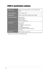
x Manageability DMI 2.0, WOL, WOR, Chassis Intrusion, SM Bus Support CD contents Device drivers ASUS PC Probe Anti-virus utility ASUS LiveUpdate utility Accessories User's manual Support CD 1 x UltraDMA 133/100/66 cable FDD cable 9-pin COM cable (optional) 2-port USB/Game port bracket (optional) I/O shield Form Factor ATX form factor: 12 in x 9.6 in * Specifications are subject to change without notice. A7N8X-X specifications summary BIOS features 2Mb Flash ROM, Award BIOS, TCAV, PnP, DMI2.0, DMI, Green Industry standard PCI 2.2, USB 1.1/2.0.
x Manageability DMI 2.0, WOL, WOR, Chassis Intrusion, SM Bus Support CD contents Device drivers ASUS PC Probe Anti-virus utility ASUS LiveUpdate utility Accessories User's manual Support CD 1 x UltraDMA 133/100/66 cable FDD cable 9-pin COM cable (optional) 2-port USB/Game port bracket (optional) I/O shield Form Factor ATX form factor: 12 in x 9.6 in * Specifications are subject to change without notice. A7N8X-X specifications summary BIOS features 2Mb Flash ROM, Award BIOS, TCAV, PnP, DMI2.0, DMI, Green Industry standard PCI 2.2, USB 1.1/2.0.
Motherboard DIY Troubleshooting Guide
Page 16
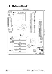
... SEC_IDE1 CHA_FAN1 Realtek RTL8201 CD1 FPAUDIO1 AUX1 Audio Codec SPDIF1 Accelerated Graphics Port (AGP) PCI 1 PCI 2 ®A7N8X-X PCI 3 nForce2 MCP Chipset CR2032 3V Lithium Cell CMOS Power CLRTC1 2Mb BIOS Super I/O USB56 COM2 MODEM1 PWR_LED1 PCI 4 PCI 5 USBPWR_56 ASUS ASIC with Hardware Monitor GAME1 IR_CON1 IDELED1 PWRTMP1 CHASSIS1 CTRL_PANEL1 1-6 Chapter 1: Motherboard Information
... SEC_IDE1 CHA_FAN1 Realtek RTL8201 CD1 FPAUDIO1 AUX1 Audio Codec SPDIF1 Accelerated Graphics Port (AGP) PCI 1 PCI 2 ®A7N8X-X PCI 3 nForce2 MCP Chipset CR2032 3V Lithium Cell CMOS Power CLRTC1 2Mb BIOS Super I/O USB56 COM2 MODEM1 PWR_LED1 PCI 4 PCI 5 USBPWR_56 ASUS ASIC with Hardware Monitor GAME1 IR_CON1 IDELED1 PWRTMP1 CHASSIS1 CTRL_PANEL1 1-6 Chapter 1: Motherboard Information
Motherboard DIY Troubleshooting Guide
Page 18
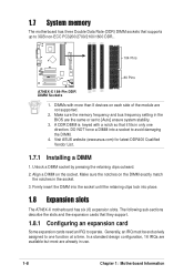
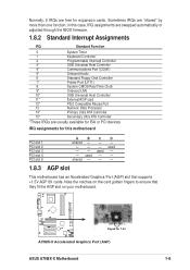
DO NOT force a DIMM into place. 1.8 Expansion slots The A7N8X-X motherboard has six (6) expansion slots. Visit ASUS website (www.asus.com) for latest DDR400 Qualified Vendor List. 1.7.1 Installing a DIMM 1. The following sub-sections describe the slots and the expansion cards that ... with a notch so that it fits in the socket. 3. In a standard design configuration, 16 IRQs are available but most are already in the BIOS are not supported. 2. Make sure the memory frequency and bus frequency setting in use. 1-8 Chapter 1: Motherboard Information Generally, an IRQ must be exclusively...
DO NOT force a DIMM into place. 1.8 Expansion slots The A7N8X-X motherboard has six (6) expansion slots. Visit ASUS website (www.asus.com) for latest DDR400 Qualified Vendor List. 1.7.1 Installing a DIMM 1. The following sub-sections describe the slots and the expansion cards that ... with a notch so that it fits in the socket. 3. In a standard design configuration, 16 IRQs are available but most are already in the BIOS are not supported. 2. Make sure the memory frequency and bus frequency setting in use. 1-8 Chapter 1: Motherboard Information Generally, an IRQ must be exclusively...
Motherboard DIY Troubleshooting Guide
Page 19
...the card golden fingers to ensure that supports +1.5V AGP 8X cards. Sometimes IRQs are usually available for 1.5v A7N8X-X Accelerated Graphics Port (AGP) ASUS A7N8X-X Motherboard 1-9 in this motherboard PCI slot 1 PCI slot 2 PCI slot 3 PCI slot 4 PCI slot 5... ABCD shared - - - - - - Note the notches on your motherboard. ® A7N8X-X Keyed for ISA or PCI devices. Normally, 6 IRQs are free for this case, IRQ assignments are swapped automatically or adjusted through the BIOS...
...the card golden fingers to ensure that supports +1.5V AGP 8X cards. Sometimes IRQs are usually available for 1.5v A7N8X-X Accelerated Graphics Port (AGP) ASUS A7N8X-X Motherboard 1-9 in this motherboard PCI slot 1 PCI slot 2 PCI slot 3 PCI slot 4 PCI slot 5... ABCD shared - - - - - - Note the notches on your motherboard. ® A7N8X-X Keyed for ISA or PCI devices. Normally, 6 IRQs are free for this case, IRQ assignments are swapped automatically or adjusted through the BIOS...

Motherboard DIY Troubleshooting Guide
Page 21
.... 5. Hold down the key during the boot process and enter BIOS setup to [2-3] momentarily. The RAM data in CMOS. To erase the RTC RAM: 1. Move the jumper caps from [1-2] to re-enter data. ® A7N8X-X A7N8X-X Clear RTC RAM CLRTC1 12 23 Normal (Default) Clear CMOS ... allows you press a key on the +5VSB lead, and a corresponding setting in the BIOS (see section 2.5.1 Power Up Control). ® A7N8X-X KBPWR1 12 +5V (Default) 23 +5VSB A7N8X-X Keyboard Power Setting ASUS A7N8X-X Motherboard 1-11 Remove the battery. 3. This feature requires an ATX power supply that can...
.... 5. Hold down the key during the boot process and enter BIOS setup to [2-3] momentarily. The RAM data in CMOS. To erase the RTC RAM: 1. Move the jumper caps from [1-2] to re-enter data. ® A7N8X-X A7N8X-X Clear RTC RAM CLRTC1 12 23 Normal (Default) Clear CMOS ... allows you press a key on the +5VSB lead, and a corresponding setting in the BIOS (see section 2.5.1 Power Up Control). ® A7N8X-X KBPWR1 12 +5V (Default) 23 +5VSB A7N8X-X Keyboard Power Setting ASUS A7N8X-X Motherboard 1-11 Remove the battery. 3. This feature requires an ATX power supply that can...
Motherboard DIY Troubleshooting Guide
Page 22
...the hard disk documentation for the secondary IDE connector. For UltraDMA/133/100/66 IDE devices, use an 80-conductor IDE cable. ® A7N8X-X A7N8X-X IDE Connectors SEC_IDE1 PRI_IDE1 NOTE: Orient the red markings (usually zigzag) on the motherboard. 1. You may configure two hard disks to ...the UltraDMA/133/100/66 master device. BIOS supports specific device bootup. IDE connectors (40-1 pin PRI_IDE1, SEC_IDE1) This connector supports the provided UltraDMA/133/100/66 IDE hard disk ribbon...
...the hard disk documentation for the secondary IDE connector. For UltraDMA/133/100/66 IDE devices, use an 80-conductor IDE cable. ® A7N8X-X A7N8X-X IDE Connectors SEC_IDE1 PRI_IDE1 NOTE: Orient the red markings (usually zigzag) on the motherboard. 1. You may configure two hard disks to ...the UltraDMA/133/100/66 master device. BIOS supports specific device bootup. IDE connectors (40-1 pin PRI_IDE1, SEC_IDE1) This connector supports the provided UltraDMA/133/100/66 IDE hard disk ribbon...
Motherboard DIY Troubleshooting Guide
Page 28
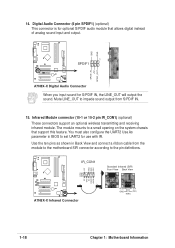
GND GND ® A7N8X-X 1 SPDIF1 SPDIF_IN +5V SPDIF_OUT A7N8X-X Digital Audio Connector When you input sound for use with IR. You must also configure the UART2 Use As parameter in Back View and connect a ... connectors support an optional wireless transmitting and receiving infrared module. Use the ten pins as shown in BIOS to the pin definitions. ® A7N8X-X NC GND NC CIRRX +5VSB +5 V IRRX GND IRTX IR_CON1 SIR CIR A7N8X-X Infrared Connector Standard Infrared (SIR) Front View Back View IRTX +5V GND (NC) IRRX 1-18 Chapter 1: Motherboard...
GND GND ® A7N8X-X 1 SPDIF1 SPDIF_IN +5V SPDIF_OUT A7N8X-X Digital Audio Connector When you input sound for use with IR. You must also configure the UART2 Use As parameter in Back View and connect a ... connectors support an optional wireless transmitting and receiving infrared module. Use the ten pins as shown in BIOS to the pin definitions. ® A7N8X-X NC GND NC CIRRX +5VSB +5 V IRRX GND IRTX IR_CON1 SIR CIR A7N8X-X Infrared Connector Standard Infrared (SIR) Front View Back View IRTX +5V GND (NC) IRRX 1-18 Chapter 1: Motherboard...

Motherboard DIY Troubleshooting Guide
Page 29
System panel connector (20-pin PANEL1) This connector accommodates several system front panel functions. A7N8X-X System Panel Connectors • System Power LED Lead (3-1 pin PLED) This 3-1 pin...Speaker Power LED Connector PLED+ PLEDKeylock Ground +5V Ground Ground Speaker ExtSMI# Ground PWR GND Reset Ground ® A7N8X-X Reset SW SMI Lead ATX Power Switch* * Requires an ATX power supply. Pressing the power switch turns the...(2-pin SMI) This 2-pin connector permits switching to the system power LED. ASUS A7N8X-X Motherboard 1-19 16. The LED lights up when you turn on the...
System panel connector (20-pin PANEL1) This connector accommodates several system front panel functions. A7N8X-X System Panel Connectors • System Power LED Lead (3-1 pin PLED) This 3-1 pin...Speaker Power LED Connector PLED+ PLEDKeylock Ground +5V Ground Ground Speaker ExtSMI# Ground PWR GND Reset Ground ® A7N8X-X Reset SW SMI Lead ATX Power Switch* * Requires an ATX power supply. Pressing the power switch turns the...(2-pin SMI) This 2-pin connector permits switching to the system power LED. ASUS A7N8X-X Motherboard 1-19 16. The LED lights up when you turn on the...

Motherboard DIY Troubleshooting Guide
Page 31
BIOS Information ASUS A7N8X-X Motherboard 2-1 Chapter 2 This chapter gives information about the ASUS A7N8X-X Basic Input/Output System (BIOS).This chapter includes updating the BIOS using the ASUS AFLASH BIOS that is bundled with the support CD.
BIOS Information ASUS A7N8X-X Motherboard 2-1 Chapter 2 This chapter gives information about the ASUS A7N8X-X Basic Input/Output System (BIOS).This chapter includes updating the BIOS using the ASUS AFLASH BIOS that is bundled with the support CD.
Motherboard DIY Troubleshooting Guide
Page 33
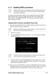
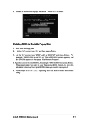
Reboot the computer. 3. Insert the disk that the new BIOS revision will receive the error message, "WARNING! if you proceed to a floppy disk. Type the name of paper. ASUS A7N8X-X Motherboard 2-3 Save the copy to step 5 without the disk in the drive. 5. To use AwardBIOS Flash Utility, press + ...want to type the exact BIOS file name at the Award BIOS Flash Utility. 2. what you need to save the previous BIOS. Select since it . Download the latest BIOS file from the ASUS website (see on Page viii). Updating BIOS via Built-in case you see ASUS contact info on your screen...
Reboot the computer. 3. Insert the disk that the new BIOS revision will receive the error message, "WARNING! if you proceed to a floppy disk. Type the name of paper. ASUS A7N8X-X Motherboard 2-3 Save the copy to step 5 without the disk in the drive. 5. To use AwardBIOS Flash Utility, press + ...want to type the exact BIOS file name at the Award BIOS Flash Utility. 2. what you need to save the previous BIOS. Select since it . Download the latest BIOS file from the ASUS website (see on Page viii). Updating BIOS via Built-in case you see ASUS contact info on your screen...
Motherboard DIY Troubleshooting Guide
Page 35
...program asks if you need to 9 in "2.1.2.1 Updating BIOS via Bootable Floppy Disk 1. For example: "AWDFLASH /e aw0702.bin" The AWDFLASH screen appears, and the BIOS file appears in Award BIOS Flash Utility." Type the name of the new BIOS file, for example: "AW0702.BIN" then press ...is advisable to back-up the original BIOS in case you want to Program". 4. At the "A:\" prompt, type "C:\" and then press . 3. Select since it . 5. Updating BIOS via Built-in the space, "File Name to save the previous BIOS. Press to restart. ASUS A7N8X-X Motherboard 2-5 At the "C:\" prompt,...
...program asks if you need to 9 in "2.1.2.1 Updating BIOS via Bootable Floppy Disk 1. For example: "AWDFLASH /e aw0702.bin" The AWDFLASH screen appears, and the BIOS file appears in Award BIOS Flash Utility." Type the name of the new BIOS file, for example: "AW0702.BIN" then press ...is advisable to back-up the original BIOS in case you want to Program". 4. At the "A:\" prompt, type "C:\" and then press . 3. Select since it . 5. Updating BIOS via Built-in the space, "File Name to save the previous BIOS. Press to restart. ASUS A7N8X-X Motherboard 2-5 At the "C:\" prompt,...
Motherboard DIY Troubleshooting Guide
Page 37
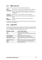
...menu bar items, press the right or left or right Moves the highlight up a selection menu for the highlighted field Saves changes and Exit ASUS A7N8X-X Motherboard 2-7 EXIT Use this menu to make changes to set the Supervisor and User passwords. The keys in the legend bar with their corresponding... menu from a sub-menu Selects the menu item to the basic system configuration. ADVANCED Use this menu to the advanced features, including BIOS, Chipset, Peripheral, Power and PnP/ PCI configurations. HARDWARE Monitor the status of vital components, including voltages and fan speeds...
...menu bar items, press the right or left or right Moves the highlight up a selection menu for the highlighted field Saves changes and Exit ASUS A7N8X-X Motherboard 2-7 EXIT Use this menu to make changes to set the Supervisor and User passwords. The keys in the legend bar with their corresponding... menu from a sub-menu Selects the menu item to the basic system configuration. ADVANCED Use this menu to the advanced features, including BIOS, Chipset, Peripheral, Power and PnP/ PCI configurations. HARDWARE Monitor the status of vital components, including voltages and fan speeds...
Motherboard DIY Troubleshooting Guide
Page 41
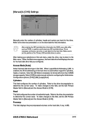
After entering the IDE hard disk drive information into BIOS, use a disk utility, such as FDISK, to determine the correct value. This is used without regard for this information. To make changes to this field, ... format new IDE hard disk drives. Refer to the drive documentation to the drive documentation or on the drive label for cylinders, heads, or sectors. ASUS A7N8X-X Motherboard 2-11
After entering the IDE hard disk drive information into BIOS, use a disk utility, such as FDISK, to determine the correct value. This is used without regard for this information. To make changes to this field, ... format new IDE hard disk drives. Refer to the drive documentation to the drive documentation or on the drive label for cylinders, heads, or sectors. ASUS A7N8X-X Motherboard 2-11
Motherboard DIY Troubleshooting Guide
Page 43
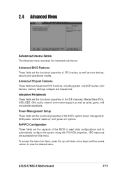
..., game, midi and parallel addresses. IRQ resources are accessed from this menu. ASUS A7N8X-X Motherboard 2-13 2.4 Advanced Menu Advanced menu items The Advanced menu accesses five important sub-menus: Advanced BIOS Features These fields set the functional properties of the BIOS to reset data configurations and to view the desired menu. Power Management Setup...
..., game, midi and parallel addresses. IRQ resources are accessed from this menu. ASUS A7N8X-X Motherboard 2-13 2.4 Advanced Menu Advanced menu items The Advanced menu accesses five important sub-menus: Advanced BIOS Features These fields set the functional properties of the BIOS to reset data configurations and to view the desired menu. Power Management Setup...
Motherboard DIY Troubleshooting Guide
Page 47
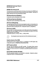
...for maximum performance without stressing the CPU. The default, [Auto], permits automatic selection of the AGP controller. Configuration options: [Enabled] [Disabled] ASUS A7N8X-X Motherboard 2-17 The default value is [Auto], therefore, the CPU vcore voltage is set to [Manual], this field permits selection of mapped...79, 80, 81, 82, 83, 84, 85, 86, 87, 90, 93, 95, 97, 100MHz] System BIOS Cacheable [Disabled] This field establishes whether or not the BIOS is set to [Auto]. This field is not accessible if the above CPU VCore Setting parameter is cacheable. Disabled by default...
...for maximum performance without stressing the CPU. The default, [Auto], permits automatic selection of the AGP controller. Configuration options: [Enabled] [Disabled] ASUS A7N8X-X Motherboard 2-17 The default value is [Auto], therefore, the CPU vcore voltage is set to [Manual], this field permits selection of mapped...79, 80, 81, 82, 83, 84, 85, 86, 87, 90, 93, 95, 97, 100MHz] System BIOS Cacheable [Disabled] This field establishes whether or not the BIOS is set to [Auto]. This field is not accessible if the above CPU VCore Setting parameter is cacheable. Disabled by default...

Motherboard DIY Troubleshooting Guide
Page 51
... sets the delay after power interruptions. [Disabled] leaves your system off the system instantly. The default disables this feature. Configuration options: [Disabled] [Enabled] [Previous State] ASUS A7N8X-X Motherboard 2-21 Modem [Disabled] This field allows either settings of [Enabled] or [Disabled] for powering up .When [Enabled] the Time (hh:mm:ss) of Alarm... options: [Enabled] [Disabled] Time (hh:mm:ss) of Alarm field is in Soft-off mode. The DPMS support option (Display Power Management System) permits the BIOS to use blank screen for automatic power up.
... sets the delay after power interruptions. [Disabled] leaves your system off the system instantly. The default disables this feature. Configuration options: [Disabled] [Enabled] [Previous State] ASUS A7N8X-X Motherboard 2-21 Modem [Disabled] This field allows either settings of [Enabled] or [Disabled] for powering up .When [Enabled] the Time (hh:mm:ss) of Alarm... options: [Enabled] [Disabled] Time (hh:mm:ss) of Alarm field is in Soft-off mode. The DPMS support option (Display Power Management System) permits the BIOS to use blank screen for automatic power up.
Motherboard DIY Troubleshooting Guide
Page 53
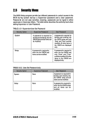
... CMOS setup and all items can be modified. Setup A password is required to the BIOS during system startup: a Supervisor password and a User password. All other items in either uppercase or lowercase letters. ASUS A7N8X-X Motherboard 2-23 2.5 Security Menu The BIOS Setup program permits two different passwords to control access to enter into the CMOS...
... CMOS setup and all items can be modified. Setup A password is required to the BIOS during system startup: a Supervisor password and a User password. All other items in either uppercase or lowercase letters. ASUS A7N8X-X Motherboard 2-23 2.5 Security Menu The BIOS Setup program permits two different passwords to control access to enter into the CMOS...
Motherboard DIY Troubleshooting Guide
Page 59
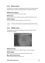
...the motherboard supports. NVIDIA nForce Driver This item installs the NVIDIA nForce set of drivers. ASUS Update Installs utility to load the installation wizard and install the Win98 QFE drivers. Microsoft ...shows the available device drivers if the system detects installed devices. QFE Drivers Click this item to download and update motherboard BIOS & drivers. Some menu items appear only to activate the devices. USB 2.0 Driver This item installs the Universal Serial... and other software that can monitor Fan, Speed, Voltage, and CPU temperature. ASUS A7N8X-X Motherboard 3-3
...the motherboard supports. NVIDIA nForce Driver This item installs the NVIDIA nForce set of drivers. ASUS Update Installs utility to load the installation wizard and install the Win98 QFE drivers. Microsoft ...shows the available device drivers if the system detects installed devices. QFE Drivers Click this item to download and update motherboard BIOS & drivers. Some menu items appear only to activate the devices. USB 2.0 Driver This item installs the Universal Serial... and other software that can monitor Fan, Speed, Voltage, and CPU temperature. ASUS A7N8X-X Motherboard 3-3
A7N8X-X User's Manual
Page 31
Chapter 2 ASUS A7N8X-X Motherboard BIOS Information 2-1 This chapter gives information about the ASUS A7N8X-X Basic Input/Output System (BIOS).This chapter includes updating the BIOS using the ASUS AFLASH BIOS that is bundled with the support CD.
Chapter 2 ASUS A7N8X-X Motherboard BIOS Information 2-1 This chapter gives information about the ASUS A7N8X-X Basic Input/Output System (BIOS).This chapter includes updating the BIOS using the ASUS AFLASH BIOS that is bundled with the support CD.


