
Motherboard DIY Troubleshooting Guide
Page 6
These devices could interrupt the grounding circuit. • Make sure that your power supply is broken, do not try to fix it , carefully read all power cables are connected. vi Contact a qualified service technician or your retailer. Operation safety • Before installing the motherboard and adding... it may become wet. • Place the product on it by yourself. If possible, disconnect all power cables from the existing system before using , contact your local power company. • If the power supply is set to the correct voltage in any damage, contact your area.
These devices could interrupt the grounding circuit. • Make sure that your power supply is broken, do not try to fix it , carefully read all power cables are connected. vi Contact a qualified service technician or your retailer. Operation safety • Before installing the motherboard and adding... it may become wet. • Place the product on it by yourself. If possible, disconnect all power cables from the existing system before using , contact your local power company. • If the power supply is set to the correct voltage in any damage, contact your area.

Motherboard DIY Troubleshooting Guide
Page 14
...are built-in for a variety of 400/333/266/200MHz DDR memory. The Super I /O functions. This header connects to an ATX 12V power supply. This connector connects the provided ribbon cable for the AMD Duron™/Athlon™/Athlon XP™ 3000+ processors. 2 NorthBridge Controller. ITE ... USB and support for wireless connections. This standard 20-pin connector connects to a GAME port module. 1-4 Chapter 1: Motherboard Information The power supply must have at 800MB/sec to 3GB of DDR DRAM, the newest memory standard with EPP and ECP capabilities. UART2 can also be directed...
...are built-in for a variety of 400/333/266/200MHz DDR memory. The Super I /O functions. This header connects to an ATX 12V power supply. This connector connects the provided ribbon cable for the AMD Duron™/Athlon™/Athlon XP™ 3000+ processors. 2 NorthBridge Controller. ITE ... USB and support for wireless connections. This standard 20-pin connector connects to a GAME port module. 1-4 Chapter 1: Motherboard Information The power supply must have at 800MB/sec to 3GB of DDR DRAM, the newest memory standard with EPP and ECP capabilities. UART2 can also be directed...

Motherboard DIY Troubleshooting Guide
Page 17
... indicator while orienting the CPU. The A7N8X supports Athlon™ XP processors with the component. 5. ASUS A7N8X Motherboard 1-7 Refer to avoid damaging them . 4. Use a grounded wrist strap or touch a safely grounded object or to a metal object, such as the power supply case, before handling components to this motherboard. ® A7N8X CPU NOTCH TO INNER CORNER AMD...
... indicator while orienting the CPU. The A7N8X supports Athlon™ XP processors with the component. 5. ASUS A7N8X Motherboard 1-7 Refer to avoid damaging them . 4. Use a grounded wrist strap or touch a safely grounded object or to a metal object, such as the power supply case, before handling components to this motherboard. ® A7N8X CPU NOTCH TO INNER CORNER AMD...
Motherboard DIY Troubleshooting Guide
Page 20
... for Front Side Bus 400/333/266. The total current consumed must NOT exceed the power supply capability (+5VSB) whether under normal condition or in low power mode) using the connected USB devices. USBPWR_12 USBPWR_34 12 23 ® A7N8X A7N8X USB Device Wake Up +5V (Default) +5VSB USBPWR_56 1 2 +5V (Default) 2 3 +5VSB 2. Set to +5VSB to...
... for Front Side Bus 400/333/266. The total current consumed must NOT exceed the power supply capability (+5VSB) whether under normal condition or in low power mode) using the connected USB devices. USBPWR_12 USBPWR_34 12 23 ® A7N8X A7N8X USB Device Wake Up +5V (Default) +5VSB USBPWR_56 1 2 +5V (Default) 2 3 +5VSB 2. Set to +5VSB to...

Motherboard DIY Troubleshooting Guide
Page 21
... process and enter BIOS setup to [2-3] momentarily. This feature requires an ATX power supply that can supply at least 1A on the keyboard (the default value is powered by the onboard button cell battery. KBPWR1 12 +5V (Default) 23 +5VSB ® A7N8X A7N8X Keyboard Power Setting ASUS A7N8X Motherboard 1-11 Move the jumper caps from [1-2] to re-enter data...
... process and enter BIOS setup to [2-3] momentarily. This feature requires an ATX power supply that can supply at least 1A on the keyboard (the default value is powered by the onboard button cell battery. KBPWR1 12 +5V (Default) 23 +5VSB ® A7N8X A7N8X Keyboard Power Setting ASUS A7N8X Motherboard 1-11 Move the jumper caps from [1-2] to re-enter data...

Motherboard DIY Troubleshooting Guide
Page 23
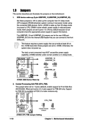
... your keyboard by pressing to disable computer keyboard-wake-up your new ATX 12V power supply can supply at least 1A on the +5VSB lead. The minimum recommended wattage is inadequate. ASUS A7N8X Motherboard 1-13 Floppy disk drive connector (34-1 pin FLOPPY1) This allows you ...to disable or enable the keyboard power up if the power supply is 230W, or 300W for a fully configured system. ATX power connectors (20-pin ATXPWR1) These ...
... your keyboard by pressing to disable computer keyboard-wake-up your new ATX 12V power supply can supply at least 1A on the +5VSB lead. The minimum recommended wattage is inadequate. ASUS A7N8X Motherboard 1-13 Floppy disk drive connector (34-1 pin FLOPPY1) This allows you ...to disable or enable the keyboard power up if the power supply is 230W, or 300W for a fully configured system. ATX power connectors (20-pin ATXPWR1) These ...

Motherboard DIY Troubleshooting Guide
Page 25
CPU_FAN1 Rotation +12V GND PWR_FAN1 CHA_FAN1 ® A7N8X A7N8X 12-Volt Cooling Fan Power Do not forget to connect the fan cables to the fan connectors on the fan connectors! 7. This requires an external detection mechanism such as a chassis ... pins. When you wish to record a chassis intrusion event. Lack of 1A~2.22A (26.64W max.) at +12V. CHASSIS1 +5Volt (Power Supply Stand By) Chassis Signal Ground ® A7N8X 1 A7N8X Chassis Open Alarm Lead ASUS A7N8X Motherboard 1-15 GND +12V Rotation GND +12V Rotation 6. DO NOT place jumper caps on the motherboard, making sure that the...
CPU_FAN1 Rotation +12V GND PWR_FAN1 CHA_FAN1 ® A7N8X A7N8X 12-Volt Cooling Fan Power Do not forget to connect the fan cables to the fan connectors on the fan connectors! 7. This requires an external detection mechanism such as a chassis ... pins. When you wish to record a chassis intrusion event. Lack of 1A~2.22A (26.64W max.) at +12V. CHASSIS1 +5Volt (Power Supply Stand By) Chassis Signal Ground ® A7N8X 1 A7N8X Chassis Open Alarm Lead ASUS A7N8X Motherboard 1-15 GND +12V Rotation GND +12V Rotation 6. DO NOT place jumper caps on the motherboard, making sure that the...

Motherboard DIY Troubleshooting Guide
Page 27
...Audio Channel 11. Mute LINE_OUT to receive stereo audio input from S/PDIF IN. ASUS A7N8X Motherboard 1-17 MODEM1 CD1 (Black) AUX1 (White) ® A7N8X A7N8X Internal Audio Connectors 12. Power Supply Thermal Sensor (2-pin PWRTMP1) This header supports a thermal sensor for optional S/...module that allows digital instead of analog sound input and output. PWRTMP1 ® A7N8X PWRTMP Ground A7N8X Power Supply Thermal Connector 13. GND GND 1 SPDIF1 ® A7N8X SPDIF_IN +5V SPDIF_OUT A7N8X Digital Audio Connector When you to impede sound output from sound sources such as ...
...Audio Channel 11. Mute LINE_OUT to receive stereo audio input from S/PDIF IN. ASUS A7N8X Motherboard 1-17 MODEM1 CD1 (Black) AUX1 (White) ® A7N8X A7N8X Internal Audio Connectors 12. Power Supply Thermal Sensor (2-pin PWRTMP1) This header supports a thermal sensor for optional S/...module that allows digital instead of analog sound input and output. PWRTMP1 ® A7N8X PWRTMP Ground A7N8X Power Supply Thermal Connector 13. GND GND 1 SPDIF1 ® A7N8X SPDIF_IN +5V SPDIF_OUT A7N8X Digital Audio Connector When you to impede sound output from sound sources such as ...

Motherboard DIY Troubleshooting Guide
Page 29
ASUS A7N8X Motherboard 1-19 The LED lights up when you turn on the BIOS or OS settings. Pressing the power switch turns the system between ON and SLEEP, or ON and SOFT OFF, depending on the system power. • Keyboard Lock Lead (2-1 pin KEYLOCK) This 2-1 pin...Connector PLED+ PLEDKeylock Ground +5V Ground Ground Speaker ExtSMI# Ground PWR GND Reset Ground ® A7N8X A7N8X System Panel Connectors Reset SW SMI Lead ATX Power Switch* * Requires an ATX power supply. • System Power LED Lead (3-1 pin PLED) This 3-1 pin connector connects to suspend mode, or "Green"...
ASUS A7N8X Motherboard 1-19 The LED lights up when you turn on the BIOS or OS settings. Pressing the power switch turns the system between ON and SLEEP, or ON and SOFT OFF, depending on the system power. • Keyboard Lock Lead (2-1 pin KEYLOCK) This 2-1 pin...Connector PLED+ PLEDKeylock Ground +5V Ground Ground Speaker ExtSMI# Ground PWR GND Reset Ground ® A7N8X A7N8X System Panel Connectors Reset SW SMI Lead ATX Power Switch* * Requires an ATX power supply. • System Power LED Lead (3-1 pin PLED) This 3-1 pin connector connects to suspend mode, or "Green"...

Motherboard DIY Troubleshooting Guide
Page 34
The program asks to save the previous BIOS to the motherboard. 8. AWDFLASH proceeds to check the new BIOS file and asks the user to program (flash) the new BIOS file to a separate file. Type a file name for the old bios and then press . Type and Press to flash the new Bios file. 6. NOTE: Do not shut off system power or unplug the supply during the flash process. 2-4 Chapter 2: BIOS Setup The AWDFLASH program backsup the file. 7.
The program asks to save the previous BIOS to the motherboard. 8. AWDFLASH proceeds to check the new BIOS file and asks the user to program (flash) the new BIOS file to a separate file. Type a file name for the old bios and then press . Type and Press to flash the new Bios file. 6. NOTE: Do not shut off system power or unplug the supply during the flash process. 2-4 Chapter 2: BIOS Setup The AWDFLASH program backsup the file. 7.

Motherboard DIY Troubleshooting Guide
Page 52
... Controlled By [Auto(ESCD)] This field sets control over the IRQ resources by default. This feature requires an ATX power supply that provides at least 1A on the +5VSB lead. Power On By PS/2 Mouse [Disabled] When set to [Enabled], this parameter allows you to use the PS/2 mouse...options: [Disabled] [Enabled] Power On By PS/2 Keyboard [Disabled] This parameter allows you to use specific keys on the keyboard to turn on the system. PCI/VGA Palette Snoop [Disabled] This field enables the PCI/VGA palette snoop. This feature requires an ATX power supply that provides at least 1A...
... Controlled By [Auto(ESCD)] This field sets control over the IRQ resources by default. This feature requires an ATX power supply that provides at least 1A on the +5VSB lead. Power On By PS/2 Mouse [Disabled] When set to [Enabled], this parameter allows you to use the PS/2 mouse...options: [Disabled] [Enabled] Power On By PS/2 Keyboard [Disabled] This parameter allows you to use specific keys on the keyboard to turn on the system. PCI/VGA Palette Snoop [Disabled] This field enables the PCI/VGA palette snoop. This feature requires an ATX power supply that provides at least 1A...


