
Motherboard DIY Troubleshooting Guide
Page 3
... and updating your BIOS 2-2 2.1.1 Using ASUS AWDFLASH to update the BIOS 2-2 2.1.2 Using ASUS AWDFLASH to find more information vii ASUS contact information vii Specifications summary ix Chapter 1 - Motherboard Info 1-1 1.1 Welcome 1-2 1.2 Package contents 1-2 1.3 Motherboard components 1-3 1.4 Motherboard layout 1-6 1.5 Before you proceed 1-7 1.6 Central ...v Safety information vi About this guide vii Conventions used in this guide vii Where to update the BIOS 2-3 Updating BIOS procedures 2-3 2.2 BIOS Setup Program 2-6 2.2.1 BIOS menu bar 2-7 2.2.2 Legend bar 2-7 iii
... and updating your BIOS 2-2 2.1.1 Using ASUS AWDFLASH to update the BIOS 2-2 2.1.2 Using ASUS AWDFLASH to find more information vii ASUS contact information vii Specifications summary ix Chapter 1 - Motherboard Info 1-1 1.1 Welcome 1-2 1.2 Package contents 1-2 1.3 Motherboard components 1-3 1.4 Motherboard layout 1-6 1.5 Before you proceed 1-7 1.6 Central ...v Safety information vi About this guide vii Conventions used in this guide vii Where to update the BIOS 2-3 Updating BIOS procedures 2-3 2.2 BIOS Setup Program 2-6 2.2.1 BIOS menu bar 2-7 2.2.2 Legend bar 2-7 iii

Motherboard DIY Troubleshooting Guide
Page 4
... the support CD 3-2 3.2.2 Software drivers and installation menus 3-3 iv Safeguards Contents 2.3 Main Menu 2-9 2.3.1 Primary Master/Slave 2-10 2.3.2 Secondary Master/Slave 2-12 2.4 Advanced Menu 2-13 2.4.1 Advanced BIOS Configuration 2-14 2.4.2 Advanced Chipset Features 2-15 2.4.3 Integrated Peripherals 2-18 2.4.4 Power Management Setup 2-20 2.4.5 PnP/PCI Configurations 2-22 2.5 Security Menu 2-23 2.5.1 Supervisor/User Set Password Table...
... the support CD 3-2 3.2.2 Software drivers and installation menus 3-3 iv Safeguards Contents 2.3 Main Menu 2-9 2.3.1 Primary Master/Slave 2-10 2.3.2 Secondary Master/Slave 2-12 2.4 Advanced Menu 2-13 2.4.1 Advanced BIOS Configuration 2-14 2.4.2 Advanced Chipset Features 2-15 2.4.3 Integrated Peripherals 2-18 2.4.4 Power Management Setup 2-20 2.4.5 PnP/PCI Configurations 2-22 2.5 Security Menu 2-23 2.5.1 Supervisor/User Set Password Table...

Motherboard DIY Troubleshooting Guide
Page 10
x Manageability DMI 2.0, WOL, WOR, Chassis Intrusion, SM Bus Support CD contents Device drivers ASUS PC Probe Anti-virus utility ASUS LiveUpdate Utility Accessories User's manual Support CD 1 x UltraDMA 33 cable 1 x UltraDMA 133/100/66 cable FDD cable 9-pin COM cable 2-port USB/Game port bracket (optional) I/O shield Form Factor ATX form factor: 12 in x 9.6 in * Specifications are subject to change without notice. A7N8X specifications summary BIOS features 2Mb Flash ROM, Award BIOS, TCAV, PnP, DMI2.0, DMI, Green Industry standard PCI 2.2, USB 1.1/2.0.
x Manageability DMI 2.0, WOL, WOR, Chassis Intrusion, SM Bus Support CD contents Device drivers ASUS PC Probe Anti-virus utility ASUS LiveUpdate Utility Accessories User's manual Support CD 1 x UltraDMA 33 cable 1 x UltraDMA 133/100/66 cable FDD cable 9-pin COM cable 2-port USB/Game port bracket (optional) I/O shield Form Factor ATX form factor: 12 in x 9.6 in * Specifications are subject to change without notice. A7N8X specifications summary BIOS features 2Mb Flash ROM, Award BIOS, TCAV, PnP, DMI2.0, DMI, Green Industry standard PCI 2.2, USB 1.1/2.0.

Motherboard DIY Troubleshooting Guide
Page 14
... paths for each IDE channel are slotted to an ATX 12V power supply. This header connects to section "2.1 Managing and updating your BIOS" on the +5V standby lead (+5VSB). 5 Floppy Disk connector. Both the primary(blue) and secondary(black) connectors are built-...in for more information) 8 South bridge controller. This 2Mb firmware contains the programmable BIOS program. (Refer to a GAME port module. 1-4 Chapter 1: Motherboard Information This standard 20-pin connector connects to prevent incorrect insertion of I ...
... paths for each IDE channel are slotted to an ATX 12V power supply. This header connects to section "2.1 Managing and updating your BIOS" on the +5V standby lead (+5VSB). 5 Floppy Disk connector. Both the primary(blue) and secondary(black) connectors are built-...in for more information) 8 South bridge controller. This 2Mb firmware contains the programmable BIOS program. (Refer to a GAME port module. 1-4 Chapter 1: Motherboard Information This standard 20-pin connector connects to prevent incorrect insertion of I ...

Motherboard DIY Troubleshooting Guide
Page 16
... CD1 FPAUDIO1 AUX1 Audio Codec SPDIF1 Accelerated Graphics Port (AGP Pro) AGP_WARN1 PCI 1 PCI 2 ® A7N8X PCI 3 nForce2 MCP Chipset CR2032 3V Lithium Cell CMOS Power CLRTC1 2Mb BIOS Super I/O USB56 COM2 MODEM1 PWR_LED1 PCI 4 PCI 5 USBPWR_56 ASUS ASIC with Hardware Monitor IR_CON1 PWRTMP1 IDELED1 GAME1 SMB1 CHASSIS1 BUZZ1 CTRL_PANEL1 1-6 Chapter 1: Motherboard Information
... CD1 FPAUDIO1 AUX1 Audio Codec SPDIF1 Accelerated Graphics Port (AGP Pro) AGP_WARN1 PCI 1 PCI 2 ® A7N8X PCI 3 nForce2 MCP Chipset CR2032 3V Lithium Cell CMOS Power CLRTC1 2Mb BIOS Super I/O USB56 COM2 MODEM1 PWR_LED1 PCI 4 PCI 5 USBPWR_56 ASUS ASIC with Hardware Monitor IR_CON1 PWRTMP1 IDELED1 GAME1 SMB1 CHASSIS1 BUZZ1 CTRL_PANEL1 1-6 Chapter 1: Motherboard Information
Motherboard DIY Troubleshooting Guide
Page 18
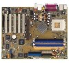
... notches on the socket. Generally, an IRQ must be exclusively assigned to avoid damaging the DIMM. 5. DO NOT force a DIMM into place. 1.8 Expansion slots The A7N8X motherboard has six (6) expansion slots. The following sequence: Sockets 1 & 3 or Sockets 2 & 3 or Sockets 1, 2 & 3. 2. In a standard design ...supported. 3. Make sure the memory frequency and bus frequency setting in the BIOS are the same or set to operate. Align a DIMM on the DIMM exactly match the notches in the socket. 3. Visit ASUS website (www.asus.com) for latest DDR400 Qualified Vendor List. 1.7.1 Installing a DIMM 1....
... notches on the socket. Generally, an IRQ must be exclusively assigned to avoid damaging the DIMM. 5. DO NOT force a DIMM into place. 1.8 Expansion slots The A7N8X motherboard has six (6) expansion slots. The following sequence: Sockets 1 & 3 or Sockets 2 & 3 or Sockets 1, 2 & 3. 2. In a standard design ...supported. 3. Make sure the memory frequency and bus frequency setting in the BIOS are the same or set to operate. Align a DIMM on the DIMM exactly match the notches in the socket. 3. Visit ASUS website (www.asus.com) for latest DDR400 Qualified Vendor List. 1.7.1 Installing a DIMM 1....

Motherboard DIY Troubleshooting Guide
Page 19
... Graphics Port (AGP8X) 20-pin bay Rib (inside slot) TOP VIEW 28-pin bay Rib ASUS A7N8X Motherboard 1-9 IRQ assignments for this case, IRQ assignments are swapped automatically or adjusted through the BIOS firmware. 1.8.2 Standard Interrupt Assignments IRQ Standard Function 0 System Timer 1 Keyboard Controller 2 Programmable Interrupt Controller 3* USB Universal Host Controller 4* Communications Port...
... Graphics Port (AGP8X) 20-pin bay Rib (inside slot) TOP VIEW 28-pin bay Rib ASUS A7N8X Motherboard 1-9 IRQ assignments for this case, IRQ assignments are swapped automatically or adjusted through the BIOS firmware. 1.8.2 Standard Interrupt Assignments IRQ Standard Function 0 System Timer 1 Keyboard Controller 2 Programmable Interrupt Controller 3* USB Universal Host Controller 4* Communications Port...

Motherboard DIY Troubleshooting Guide
Page 21
Replace the jumper cap to re-enter data. ® A7N8X A7N8X Clear RTC RAM CLRTC1 12 23 Normal (Default) Clear CMOS 4. Hold down the key during the boot process and enter BIOS setup to the original position, [1-2]. 4. Clear RTC RAM (CLRTC1) (optional) This jumper clears the Real Time Clock (RTC...Move the jumper caps from [1-2] to pins 2-3 (+5VSB) if you press a key on the +5VSB lead, and a corresponding setting in the BIOS (see section 2.5.1 Power Up Control). KBPWR1 12 +5V (Default) 23 +5VSB ® A7N8X A7N8X Keyboard Power Setting ASUS A7N8X Motherboard 1-11 3.
Replace the jumper cap to re-enter data. ® A7N8X A7N8X Clear RTC RAM CLRTC1 12 23 Normal (Default) Clear CMOS 4. Hold down the key during the boot process and enter BIOS setup to the original position, [1-2]. 4. Clear RTC RAM (CLRTC1) (optional) This jumper clears the Real Time Clock (RTC...Move the jumper caps from [1-2] to pins 2-3 (+5VSB) if you press a key on the +5VSB lead, and a corresponding setting in the BIOS (see section 2.5.1 Power Up Control). KBPWR1 12 +5V (Default) 23 +5VSB ® A7N8X A7N8X Keyboard Power Setting ASUS A7N8X Motherboard 1-11 3.

Motherboard DIY Troubleshooting Guide
Page 22
...connector and another UltraDMA/133/100/66 cable. For UltraDMA/133/100/66 IDE devices, use an 80-conductor IDE cable. ® A7N8X A7N8X IDE Connectors SEC_IDE1 PRI_IDE1 NOTE: Orient the red markings (usually zigzag) on each IDE connector is recommended that you connect the cables.... BIOS supports specific device bootup. If you must configure the second drive as a slave device by setting its jumper accordingly. IDE connectors (40-1 ...
...connector and another UltraDMA/133/100/66 cable. For UltraDMA/133/100/66 IDE devices, use an 80-conductor IDE cable. ® A7N8X A7N8X IDE Connectors SEC_IDE1 PRI_IDE1 NOTE: Orient the red markings (usually zigzag) on each IDE connector is recommended that you connect the cables.... BIOS supports specific device bootup. If you must configure the second drive as a slave device by setting its jumper accordingly. IDE connectors (40-1 ...

Motherboard DIY Troubleshooting Guide
Page 28
...pin IR_CON1) These connectors support an optional wireless transmitting and receiving infrared module. You must also configure the UART2 Use As parameter in BIOS to act as shown in Back View and connect a ribbon cable from the module to the motherboard SIR connector according to a ...multi-device bus that support this feature. SMBus Connector (6-1 pin SMB1) This connector supports SMBus (System Management Bus) devices. IR_CON1 SIR CIR ® A7N8X A7N8X Infrared Connector NC GND NC CIRRX +5VSB +5 V IRRX GND IRTX Standard Infrared (SIR) Front View Back View IRTX +5V GND (NC) IRRX 15...
...pin IR_CON1) These connectors support an optional wireless transmitting and receiving infrared module. You must also configure the UART2 Use As parameter in BIOS to act as shown in Back View and connect a ribbon cable from the module to the motherboard SIR connector according to a ...multi-device bus that support this feature. SMBus Connector (6-1 pin SMB1) This connector supports SMBus (System Management Bus) devices. IR_CON1 SIR CIR ® A7N8X A7N8X Infrared Connector NC GND NC CIRRX +5VSB +5 V IRRX GND IRTX Standard Infrared (SIR) Front View Back View IRTX +5V GND (NC) IRRX 15...

Motherboard DIY Troubleshooting Guide
Page 29
The LED lights up when you turn on the BIOS or OS settings. Pressing the power switch turns the ...OFF. System panel connector (20-pin PANEL1) This connector accommodates several system front panel functions. 16. ASUS A7N8X Motherboard 1-19 Pressing the power switch while in which system activity is instantly decreased to save power ...Speaker Power LED Connector PLED+ PLEDKeylock Ground +5V Ground Ground Speaker ExtSMI# Ground PWR GND Reset Ground ® A7N8X A7N8X System Panel Connectors Reset SW SMI Lead ATX Power Switch* * Requires an ATX power supply. • System...
The LED lights up when you turn on the BIOS or OS settings. Pressing the power switch turns the ...OFF. System panel connector (20-pin PANEL1) This connector accommodates several system front panel functions. 16. ASUS A7N8X Motherboard 1-19 Pressing the power switch while in which system activity is instantly decreased to save power ...Speaker Power LED Connector PLED+ PLEDKeylock Ground +5V Ground Ground Speaker ExtSMI# Ground PWR GND Reset Ground ® A7N8X A7N8X System Panel Connectors Reset SW SMI Lead ATX Power Switch* * Requires an ATX power supply. • System...

Motherboard DIY Troubleshooting Guide
Page 31
Chapter 2 This chapter gives information about the ASUS A7N8X Basic Input/Output System (BIOS).This chapter includes updating the BIOS using the ASUS AFLASH BIOS that is bundled with the support CD. BIOS Information ASUS A7N8X Motherboard 2-1
Chapter 2 This chapter gives information about the ASUS A7N8X Basic Input/Output System (BIOS).This chapter includes updating the BIOS using the ASUS AFLASH BIOS that is bundled with the support CD. BIOS Information ASUS A7N8X Motherboard 2-1

Motherboard DIY Troubleshooting Guide
Page 32
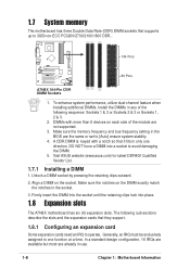
... to copy AWDFLASH.EXE to the boot disk you reboot using a floppy disk in order to open DOS mode. 3. Another series model A7N8X Deluxe uses the BIOS file for 2Mb flash ROM. The PCB (Printed Circuit Board) version is recommended that you created. If this may cause boot problems. Just... be loaded when you encounter problems while updating the new BIOS, DO NOT turn off the system because this happens, call the ASUS service center for support. 2-2 Chapter 2: BIOS Setup If you boot from the floppy disk. To determine the BIOS version of your motherboard, check the last four numbers of...
... to copy AWDFLASH.EXE to the boot disk you reboot using a floppy disk in order to open DOS mode. 3. Another series model A7N8X Deluxe uses the BIOS file for 2Mb flash ROM. The PCB (Printed Circuit Board) version is recommended that you created. If this may cause boot problems. Just... be loaded when you encounter problems while updating the new BIOS, DO NOT turn off the system because this happens, call the ASUS service center for support. 2-2 Chapter 2: BIOS Setup If you boot from the floppy disk. To determine the BIOS version of your motherboard, check the last four numbers of...
Motherboard DIY Troubleshooting Guide
Page 33
...the motherboard and you see ASUS contact info on a piece of the new BIOS file, for reference only. Reboot the computer. 3. Insert the disk that the new BIOS revision will receive the error message, "WARNING! Select since it . 2.1.2 Updating BIOS procedures Update the BIOS only if you have ... create more problems ! The BIOS information in the above screen is advisable to back-up the original BIOS in case you want to a floppy disk. Save the copy to save the previous BIOS. Write down the BIOS file name on Page viii). Type the name of paper. ASUS A7N8X Motherboard 2-3
...the motherboard and you see ASUS contact info on a piece of the new BIOS file, for reference only. Reboot the computer. 3. Insert the disk that the new BIOS revision will receive the error message, "WARNING! Select since it . 2.1.2 Updating BIOS procedures Update the BIOS only if you have ... create more problems ! The BIOS information in the above screen is advisable to back-up the original BIOS in case you want to a floppy disk. Save the copy to save the previous BIOS. Write down the BIOS file name on Page viii). Type the name of paper. ASUS A7N8X Motherboard 2-3

Motherboard DIY Troubleshooting Guide
Page 34
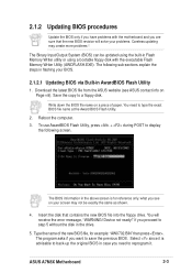
6. Type a file name for the old bios and then press . Type and Press to a separate file. NOTE: Do not shut off system power or unplug the supply during the flash process. 2-4 Chapter 2: BIOS Setup The program asks to save the previous BIOS to flash the new Bios file. AWDFLASH proceeds to check the new BIOS file and asks the user to program (flash) the new BIOS file to the motherboard. 8. The AWDFLASH program backsup the file. 7.
6. Type a file name for the old bios and then press . Type and Press to a separate file. NOTE: Do not shut off system power or unplug the supply during the flash process. 2-4 Chapter 2: BIOS Setup The program asks to save the previous BIOS to flash the new Bios file. AWDFLASH proceeds to check the new BIOS file and asks the user to program (flash) the new BIOS file to the motherboard. 8. The AWDFLASH program backsup the file. 7.
Motherboard DIY Troubleshooting Guide
Page 35
..."AWDFLASH /qi BIOSFILE" and then . Select since it . 5. ASUS A7N8X Motherboard 2-5 Press to save the previous BIOS. At the "A:\" prompt, type "C:\" and then press . 3. The program asks if you want to restart. 2.1.2.2 Updating BIOS via Built-in case you need to reprogram it is advisable to Program...". 4. Boot from the floppy disk. 2. Type the name of the new BIOS file, for example: "AW0702.BIN" then press . Follow steps 6 to 9 in "2.1.2.1 Updating BIOS via Bootable Floppy Disk 1. For example: "AWDFLASH /qi aw0702.bin" The AWDFLASH screen appears...
..."AWDFLASH /qi BIOSFILE" and then . Select since it . 5. ASUS A7N8X Motherboard 2-5 Press to save the previous BIOS. At the "A:\" prompt, type "C:\" and then press . 3. The program asks if you want to restart. 2.1.2.2 Updating BIOS via Built-in case you need to reprogram it is advisable to Program...". 4. Boot from the floppy disk. 2. Type the name of the new BIOS file, for example: "AW0702.BIN" then press . Follow steps 6 to 9 in "2.1.2.1 Updating BIOS via Bootable Floppy Disk 1. For example: "AWDFLASH /qi aw0702.bin" The AWDFLASH screen appears...
Motherboard DIY Troubleshooting Guide
Page 36
...the Power-On Self Test (POST) to the power management settings. You can also restart by pressing the reset button on your screen. 2-6 Chapter 2: BIOS Setup Even if you are installing a motherboard, reconfiguring your system, or prompted to enter Setup after POST, restart the system by pressing + + ,...a menudriven program, which means you can scroll through the various sub-menus and make your selections among the predetermined choices. Use the BIOS Setup program when you are not prompted to use as easy to reconfigure your system using the provided utility described in the future. ...
...the Power-On Self Test (POST) to the power management settings. You can also restart by pressing the reset button on your screen. 2-6 Chapter 2: BIOS Setup Even if you are installing a motherboard, reconfiguring your system, or prompted to enter Setup after POST, restart the system by pressing + + ,...a menudriven program, which means you can scroll through the various sub-menus and make your selections among the predetermined choices. Use the BIOS Setup program when you are not prompted to use as easy to reconfigure your system using the provided utility described in the future. ...

Motherboard DIY Troubleshooting Guide
Page 37
... and Exit ASUS A7N8X Motherboard 2-7 EXIT Use this menu to exit the Setup MONITOR program. ADVANCED Use this menu to make changes to the basic system configuration. The keys in the legend bar with the following selections: MAIN Use this menu to enable and make changes to the advanced features, including BIOS, Chipset...
... and Exit ASUS A7N8X Motherboard 2-7 EXIT Use this menu to exit the Setup MONITOR program. ADVANCED Use this menu to make changes to the basic system configuration. The keys in the legend bar with the following selections: MAIN Use this menu to enable and make changes to the advanced features, including BIOS, Chipset...

Motherboard DIY Troubleshooting Guide
Page 38
Scroll bar When a scroll bar appears to the right of a help In addition to the Item Specific Help window, the BIOS setup program also provides a General Help screen. Press to display the first page, press to go to the main menu. Sub-menu Note that a ...each menu. The General Help screen lists the legend keys and their corresponding functions. To exit the help text for the currently highlighted field. 2-8 Chapter 2: BIOS Setup To display a sub-menu, move the highlight to scroll through the various menus and sub-menus. Saving changes and exiting the Setup program See...
Scroll bar When a scroll bar appears to the right of a help In addition to the Item Specific Help window, the BIOS setup program also provides a General Help screen. Press to display the first page, press to go to the main menu. Sub-menu Note that a ...each menu. The General Help screen lists the legend keys and their corresponding functions. To exit the help text for the currently highlighted field. 2-8 Chapter 2: BIOS Setup To display a sub-menu, move the highlight to scroll through the various menus and sub-menus. Saving changes and exiting the Setup program See...

Motherboard DIY Troubleshooting Guide
Page 40
IDE Primary Master/Slave [Auto] Select [Auto] to recognize the installed hard disk. 2-10 Chapter 2: BIOS Setup If no drive is not already detected. Incorrect settings may cause the system to fail to automatically detect an IDE hard disk drive. Select [... too old or too new. If the hard disk was already formatted on this may be because the hard disk drive is successful, the setup BIOS automatically fills in order to configure a hard disk drive, make sure you are removing a drive and not replacing it, select [None]. 2.3.1 Primary Master/Slave IDE...
IDE Primary Master/Slave [Auto] Select [Auto] to recognize the installed hard disk. 2-10 Chapter 2: BIOS Setup If no drive is not already detected. Incorrect settings may cause the system to fail to automatically detect an IDE hard disk drive. Select [... too old or too new. If the hard disk was already formatted on this may be because the hard disk drive is successful, the setup BIOS automatically fills in order to configure a hard disk drive, make sure you are removing a drive and not replacing it, select [None]. 2.3.1 Primary Master/Slave IDE...


