User Guide
Page 15
...2008/IMR PIKE 2008 Description LSI 8-port SAS2 6G RAID card LSI 8-port SAS2 6G RAID card LSI 8-port SAS2 6G RAID card ASUS Z9PH-D16, Z9PH-D16/FDR 1-3 The motherboard delivers a host of new features and latest technologies, making it , check the items in the long line ...of the above items is damaged or missing, contact your motherboard package for buying an ASUS® Z9PH-D16 Series motherboard! Before you for the following items. Standard Bulk Pack Z9PH-D16 Z9PH-D16(C602-J) Support CD 1 1 Application CD Mellanox CD ASWM Enterprise SDVD 1 1 ASMB6-iKVM SDVD 1 ...
...2008/IMR PIKE 2008 Description LSI 8-port SAS2 6G RAID card LSI 8-port SAS2 6G RAID card LSI 8-port SAS2 6G RAID card ASUS Z9PH-D16, Z9PH-D16/FDR 1-3 The motherboard delivers a host of new features and latest technologies, making it , check the items in the long line ...of the above items is damaged or missing, contact your motherboard package for buying an ASUS® Z9PH-D16 Series motherboard! Before you for the following items. Standard Bulk Pack Z9PH-D16 Z9PH-D16(C602-J) Support CD 1 1 Application CD Mellanox CD ASWM Enterprise SDVD 1 1 ASMB6-iKVM SDVD 1 ...
User Guide
Page 17
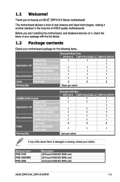
... solution The motherboard comes with a host of system memory for your computer to meet the higher bandwidth requirements of current bus systems. ASUS Z9PH-D16, Z9PH-D16/FDR 1-5 PCIe 3.0 The motherboard supports the latest PCIe 3.0 device, which uses a specially designed buffer to reduce the data load... Additionally, get enhanced scalability, faster data retrieval, double the bandwidth of server and workstation applications. DDR3 memory support The Z9PH-D16, Z9PH-D16/FDR supports DDR3 memory that features data transfer rates of 1600/1333/1066 MHz to run on the CPU loading and ...
... solution The motherboard comes with a host of system memory for your computer to meet the higher bandwidth requirements of current bus systems. ASUS Z9PH-D16, Z9PH-D16/FDR 1-5 PCIe 3.0 The motherboard supports the latest PCIe 3.0 device, which uses a specially designed buffer to reduce the data load... Additionally, get enhanced scalability, faster data retrieval, double the bandwidth of server and workstation applications. DDR3 memory support The Z9PH-D16, Z9PH-D16/FDR supports DDR3 memory that features data transfer rates of 1600/1333/1066 MHz to run on the CPU loading and ...
User Guide
Page 20
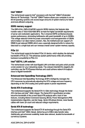
Chapter summary 2 2.1 Before you proceed 2-3 2.2 Motherboard overview 2-4 2.3 Central Processing Unit (CPU 2-8 2.4 System memory 2-14 2.5 Expansion slots 2-17 2.6 Jumpers 2-21 2.7 Connectors 2-25 ASUS Z9PH-D16, Z9PH-D16/FDR
Chapter summary 2 2.1 Before you proceed 2-3 2.2 Motherboard overview 2-4 2.3 Central Processing Unit (CPU 2-8 2.4 System memory 2-14 2.5 Expansion slots 2-17 2.6 Jumpers 2-21 2.7 Connectors 2-25 ASUS Z9PH-D16, Z9PH-D16/FDR
User Guide
Page 21
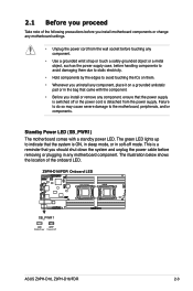
... damage to avoid touching the ICs on them due to static electricity. • Hold components by the edges to the motherboard, peripherals, and/or components. ASUS Z9PH-D16, Z9PH-D16/FDR 2-3 The green LED lights up to indicate that the system is a reminder that you should shut down the system and unplug the power cable...
... damage to avoid touching the ICs on them due to static electricity. • Hold components by the edges to the motherboard, peripherals, and/or components. ASUS Z9PH-D16, Z9PH-D16/FDR 2-3 The green LED lights up to indicate that the system is a reminder that you should shut down the system and unplug the power cable...

User Guide
Page 23
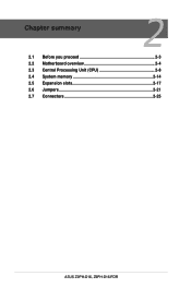
2.2.3 Motherboard layout Z9PH-D16 Z9PH-D16/FDR ASUS Z9PH-D16, Z9PH-D16/FDR 2-5
2.2.3 Motherboard layout Z9PH-D16 Z9PH-D16/FDR ASUS Z9PH-D16, Z9PH-D16/FDR 2-5
User Guide
Page 25
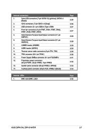
...-4 [Gray]) 3. USB connector (5-1 pin USB3; BMC LED (BMC_LED) Page 2-26 2-26 2-27 2-27 2-28 2-28 2-29 2-29 2-30 2-30 2-31 2-32 2-33 2-34 Page 2-35 ASUS Z9PH-D16, Z9PH-D16/FDR 2-7 TPM connector (20-1 pin TPM1) 11.
...-4 [Gray]) 3. USB connector (5-1 pin USB3; BMC LED (BMC_LED) Page 2-26 2-26 2-27 2-27 2-28 2-28 2-29 2-29 2-30 2-30 2-31 2-32 2-33 2-34 Page 2-35 ASUS Z9PH-D16, Z9PH-D16/FDR 2-7 TPM connector (20-1 pin TPM1) 11.

User Guide
Page 27
Press the right load lever with your thumb (C), then move it to the left load lever with your thumb (A), then move it to the socket pins, do not remove the PnP cap unless you are installing a CPU. Press the left (B) until it is released from the retention tab. Slightly lift the load lever in the direction of the arrow. 4. ASUS Z9PH-D16, Z9PH-D16/FDR E C D 2-9 Load lever 3. Lift the load lever in the direction of the arrow (E). 2. A B To prevent damage to the right (D) until it is released from the retention tab.
Press the right load lever with your thumb (C), then move it to the left load lever with your thumb (A), then move it to the socket pins, do not remove the PnP cap unless you are installing a CPU. Press the left (B) until it is released from the retention tab. Slightly lift the load lever in the direction of the arrow. 4. ASUS Z9PH-D16, Z9PH-D16/FDR E C D 2-9 Load lever 3. Lift the load lever in the direction of the arrow (E). 2. A B To prevent damage to the right (D) until it is released from the retention tab.

User Guide
Page 29
Insert the right load lever under the retention tab (M). Push down the right load lever (J), ensuring that the edge of the load plate is fixed by the lever (K). M L ASUS Z9PH-D16, Z9PH-D16/FDR 2-11 Push down the left load lever (L), and then insert the lever under the retention tab. 10. 8. K J 9.
Insert the right load lever under the retention tab (M). Push down the right load lever (J), ensuring that the edge of the load plate is fixed by the lever (K). M L ASUS Z9PH-D16, Z9PH-D16/FDR 2-11 Push down the left load lever (L), and then insert the lever under the retention tab. 10. 8. K J 9.

User Guide
Page 31
When the four screws are attached, tighten them one by one to the motherboard. ASUS Z9PH-D16, Z9PH-D16/FDR 2-13 A B B A Tighten the four heatsink screws in a diagonal sequence. Place the heatsink on the motherboard. 2. 2.3.2 Installing the CPU heatsink To install the CPU heatsink: 1. Twist each of the installed CPU, ensuring that the four fasteners match the holes on top of the four screws with a Philips (cross) screwdriver just enough to attach the heatsink to completely secure the heatsink.
When the four screws are attached, tighten them one by one to the motherboard. ASUS Z9PH-D16, Z9PH-D16/FDR 2-13 A B B A Tighten the four heatsink screws in a diagonal sequence. Place the heatsink on the motherboard. 2. 2.3.2 Installing the CPU heatsink To install the CPU heatsink: 1. Twist each of the installed CPU, ensuring that the four fasteners match the holes on top of the four screws with a Philips (cross) screwdriver just enough to attach the heatsink to completely secure the heatsink.
User Guide
Page 33
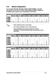
... X 2 DIMMs X 4 DIMMs X X 8 DIMMs X X X X 12 DIMMs X X X X X X 16 DIMMs X X X X X X X X 2 CPU Configuration DIMM_E2 DIMM_E1 DIMM_F2 DIMM_F1 DIMM_G2 DIMM_G1 DIMM_H2 DIMM_H1 1 DIMMs 2 DIMMs X 4 DIMMs X X 8 DIMMs X X X X 12 DIMMs X X X X X X 16 DIMMs X X X X X X X X ASUS Z9PH-D16, Z9PH-D16/FDR 2-15 For optimum compatibility, it is recommended that you obtain memory modules from slot A1 and B1 (light blue). • Always install DIMMs with...
... X 2 DIMMs X 4 DIMMs X X 8 DIMMs X X X X 12 DIMMs X X X X X X 16 DIMMs X X X X X X X X 2 CPU Configuration DIMM_E2 DIMM_E1 DIMM_F2 DIMM_F1 DIMM_G2 DIMM_G1 DIMM_H2 DIMM_H1 1 DIMMs 2 DIMMs X 4 DIMMs X X 8 DIMMs X X X X 12 DIMMs X X X X X X 16 DIMMs X X X X X X X X ASUS Z9PH-D16, Z9PH-D16/FDR 2-15 For optimum compatibility, it is recommended that you obtain memory modules from slot A1 and B1 (light blue). • Always install DIMMs with...
User Guide
Page 35
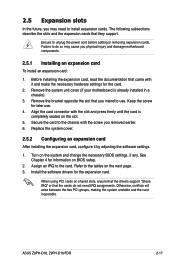
Align the card connector with the slot and press firmly until the card is already installed in a chassis). 3. ASUS Z9PH-D16, Z9PH-D16/FDR 2-17 Remove the system unit cover (if your motherboard is completely seated on the slot. 5. Keep the screw for the expansion card. Install the ...
Align the card connector with the slot and press firmly until the card is already installed in a chassis). 3. ASUS Z9PH-D16, Z9PH-D16/FDR 2-17 Remove the system unit cover (if your motherboard is completely seated on the slot. 5. Keep the screw for the expansion card. Install the ...

User Guide
Page 37
... RAID settings: 1. After the system successfully enters the OS, power off the system and disengage the original module. 2. Reboot the system to Chapter 6 RAID Configuration. ASUS Z9PH-D16, Z9PH-D16/FDR 2-19 Changing the module for Intel SCU Protocol Enabled W/O ASRK SATA (3Gb/s) ASRK #1 SATA/SAS (3Gb/s) ASRK #2 SATA/SAS (3Gb/s) Ports 4 ports 4 ports 4 ports...
... RAID settings: 1. After the system successfully enters the OS, power off the system and disengage the original module. 2. Reboot the system to Chapter 6 RAID Configuration. ASUS Z9PH-D16, Z9PH-D16/FDR 2-19 Changing the module for Intel SCU Protocol Enabled W/O ASRK SATA (3Gb/s) ASRK #1 SATA/SAS (3Gb/s) ASRK #2 SATA/SAS (3Gb/s) Ports 4 ports 4 ports 4 ports...
User Guide
Page 39
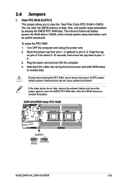
... RTC RAM (CLRTC1) This jumper allows you to clear the CMOS RTC RAM data. The onboard button cell battery powers the RAM data in CMOS. ASUS Z9PH-D16, Z9PH-D16/FDR 2-21
... RTC RAM (CLRTC1) This jumper allows you to clear the CMOS RTC RAM data. The onboard button cell battery powers the RAM data in CMOS. ASUS Z9PH-D16, Z9PH-D16/FDR 2-21
User Guide
Page 41
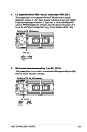
... enterprise 3.0 RAID. LSI MegaRAID or Intel RSTe selection jumper (3-pin RAID_SEL1) This jumper allows you want to use the LSI MegaRAID software RAID Utility (default); ASUS Z9PH-D16, Z9PH-D16/FDR 2-23 Place the jumper caps over pins 1-2 if you to select the PCH SATA RAID mode to quickly recover the Intel Management Engine (ME...
... enterprise 3.0 RAID. LSI MegaRAID or Intel RSTe selection jumper (3-pin RAID_SEL1) This jumper allows you want to use the LSI MegaRAID software RAID Utility (default); ASUS Z9PH-D16, Z9PH-D16/FDR 2-23 Place the jumper caps over pins 1-2 if you to select the PCH SATA RAID mode to quickly recover the Intel Management Engine (ME...

User Guide
Page 43
... VGAcompatible devices. 5. Refer to the table below for a VGA monitor or other serial devices. 6. 2.7 Connectors 2.7.1 Rear panel connectors 1 2 3 4 5 6 1. Serial (COM1) port. ASUS Z9PH-D16, Z9PH-D16/FDR 2-25 Video Graphics Adapter port. InfiniBand (QSFP). (Z9PH-D16/FDR only) This port allows connection with a QSFP cable to a Local Area Network (LAN) through a network hub for the LAN port...
... VGAcompatible devices. 5. Refer to the table below for a VGA monitor or other serial devices. 6. 2.7 Connectors 2.7.1 Rear panel connectors 1 2 3 4 5 6 1. Serial (COM1) port. ASUS Z9PH-D16, Z9PH-D16/FDR 2-25 Video Graphics Adapter port. InfiniBand (QSFP). (Z9PH-D16/FDR only) This port allows connection with a QSFP cable to a Local Area Network (LAN) through a network hub for the LAN port...
User Guide
Page 45
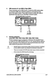
Connect the USB module cables to connectors USB3, then install the modules to the fan connectors on the fan connectors! • All fans feature the ASUS Smart Fan technology. Connect the fan cables to a slot opening at the back of 3.15 A-6.66 A (53.28 W max.) at +12V. ...of each cable matches the ground pin of the connector. • DO NOT forget to connect the fan cables to 480 Mbps connection speed. 4. ASUS Z9PH-D16, Z9PH-D16/FDR 2-27 USB connector (5-1 pin USB3; A-Type USB4) These connectors are not jumpers! Insufficient air flow inside the system may damage the motherboard ...
Connect the USB module cables to connectors USB3, then install the modules to the fan connectors on the fan connectors! • All fans feature the ASUS Smart Fan technology. Connect the fan cables to a slot opening at the back of 3.15 A-6.66 A (53.28 W max.) at +12V. ...of each cable matches the ground pin of the connector. • DO NOT forget to connect the fan cables to 480 Mbps connection speed. 4. ASUS Z9PH-D16, Z9PH-D16/FDR 2-27 USB connector (5-1 pin USB3; A-Type USB4) These connectors are not jumpers! Insufficient air flow inside the system may damage the motherboard ...

User Guide
Page 47
ASMB6 header (ASMB6) The ASMB6 connector on the motherboard supports an ASUS® ASRK module (optional). ASRK header (ASRK1) The ASRK1 connector on the motherboard supports an ASUS® Server Management Board 6 Series (ASMB6, optional). 8. ASRK module support ASRK#1 and #2 only. ASUS Z9PH-D16, Z9PH-D16/FDR 2-29 7.
ASMB6 header (ASMB6) The ASMB6 connector on the motherboard supports an ASUS® ASRK module (optional). ASRK header (ASRK1) The ASRK1 connector on the motherboard supports an ASUS® Server Management Board 6 Series (ASMB6, optional). 8. ASRK module support ASRK#1 and #2 only. ASUS Z9PH-D16, Z9PH-D16/FDR 2-29 7.
User Guide
Page 49
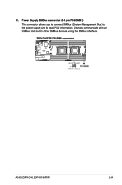
11. GND BMC_SYNC PSU_ALERT# 12C1SCL_PB 12C1SDA_PB ASUS Z9PH-D16, Z9PH-D16/FDR 2-31 Power Supply SMBus connector (6-1 pin PSUSMB1) This connector allows you to connect SMBus (System Management Bus) to the power supply unit to read PSU information. Devices communicate with an SMBus host and/or other SMBus devices using the SMBus interface.
11. GND BMC_SYNC PSU_ALERT# 12C1SCL_PB 12C1SDA_PB ASUS Z9PH-D16, Z9PH-D16/FDR 2-31 Power Supply SMBus connector (6-1 pin PSUSMB1) This connector allows you to connect SMBus (System Management Bus) to the power supply unit to read PSU information. Devices communicate with an SMBus host and/or other SMBus devices using the SMBus interface.

User Guide
Page 51
... functions. 1. Hard disk drive activity LED (2-pin HDDLED) This 2-pin connector is for the HDD Activity LED. Proprietary power button/soft-off the system power. ASUS Z9PH-D16, Z9PH-D16/FDR 2-33 System warning speaker (4-pin SPEAKER) This 4-pin connector is for the chassis-mounted system warning speaker. Pressing the power button turns the system...
... functions. 1. Hard disk drive activity LED (2-pin HDDLED) This 2-pin connector is for the HDD Activity LED. Proprietary power button/soft-off the system power. ASUS Z9PH-D16, Z9PH-D16/FDR 2-33 System warning speaker (4-pin SPEAKER) This 4-pin connector is for the chassis-mounted system warning speaker. Pressing the power button turns the system...

User Guide
Page 53
2.8 Internal LEDs 1. ASUS Z9PH-D16, Z9PH-D16/FDR 2-35 BMC LED (BMC_LED) The BMC connector on the motherboard supports an ASUS® Server Management Board 6 Series (ASMB6).
2.8 Internal LEDs 1. ASUS Z9PH-D16, Z9PH-D16/FDR 2-35 BMC LED (BMC_LED) The BMC connector on the motherboard supports an ASUS® Server Management Board 6 Series (ASMB6).

