

User Guide
Page 15
Package contents Check your motherboard package for the following items User Manual ASUS Z97-WS motherboard User manual Support DVD 8 x Serial ATA 6 Gb/s cables COM port bracket 1 x ASUS SLI™ bridge connector 1 x ASUS 4-Way SLI™ bridge connector 1 x ASUS 3-Way SLI™ bridge connector 1 x 2-in-1 Q-connector 1 x I/O Shield xv
Package contents Check your motherboard package for the following items User Manual ASUS Z97-WS motherboard User manual Support DVD 8 x Serial ATA 6 Gb/s cables COM port bracket 1 x ASUS SLI™ bridge connector 1 x ASUS 4-Way SLI™ bridge connector 1 x ASUS 3-Way SLI™ bridge connector 1 x 2-in-1 Q-connector 1 x I/O Shield xv
User Guide
Page 30
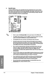
... default settings. • We recommend that are not compatible with ones recommended in the Memory QVL (Qualified Vendors Lists) in this user manual or at www.asus.com. • If you turn off the computer and unplug the power cord for about 30 seconds for the system to test ...failsafe settings. button to boot after turning on the computer. If the installed DIMMs still fail to boot and load the BIOS default settings. Z97-WS Z97-WS MemOK! It takes about 5-10 seconds. • If your system fails to memory tuning requirement, the system automatically reboots when each timing ...
... default settings. • We recommend that are not compatible with ones recommended in the Memory QVL (Qualified Vendors Lists) in this user manual or at www.asus.com. • If you turn off the computer and unplug the power cord for about 30 seconds for the system to test ...failsafe settings. button to boot after turning on the computer. If the installed DIMMs still fail to boot and load the BIOS default settings. Z97-WS Z97-WS MemOK! It takes about 5-10 seconds. • If your system fails to memory tuning requirement, the system automatically reboots when each timing ...
User Guide
Page 42
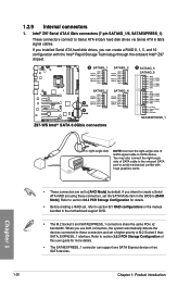
... both connectors, the system automatically detects the devices connected to these connectors, set , refer to section 5.1 RAID configurations or the manual bundled in the BIOS to M.2 Socket 3 than SATA_EXPRESS_1 interface. Refer to [AHCI Mode] by default. When you can support one... 3.6.3 PCH Storage Configuration of this user guide for details. • Before creating a RAID set the SATA Mode item in the motherboard support DVD. • The M.2 Socket 3 and SATAEXPRESS_1 connectors share the same PCIe x2 bandwidth. Z97-WS A SATA6G_1 GND RSATA_TXP1 RSATA_TXN1 GND RSATA_RXN1...
... both connectors, the system automatically detects the devices connected to these connectors, set , refer to section 5.1 RAID configurations or the manual bundled in the BIOS to M.2 Socket 3 than SATA_EXPRESS_1 interface. Refer to [AHCI Mode] by default. When you can support one... 3.6.3 PCH Storage Configuration of this user guide for details. • Before creating a RAID set the SATA Mode item in the motherboard support DVD. • The M.2 Socket 3 and SATAEXPRESS_1 connectors share the same PCIe x2 bandwidth. Z97-WS A SATA6G_1 GND RSATA_TXP1 RSATA_TXN1 GND RSATA_RXN1...

User Guide
Page 73
... settings, advanced power management, and boot device configuration that are needed for this user manual refers to enable a more flexible and convenient mouse input. We strongly recommend that...setup BIOS setup 3.1 Knowing BIOS 3 The new ASUS UEFI BIOS is a Unified Extensible Interface that complies with UEFI architecture, offering a user-friendly interface that goes beyond the traditional keyboardonly BIOS ...component that you change the default BIOS settings except in the motherboard CMOS. Chapter 3 Z97-WS 3-1 You can easily navigate the new UEFI BIOS with the help of a trained ...
... settings, advanced power management, and boot device configuration that are needed for this user manual refers to enable a more flexible and convenient mouse input. We strongly recommend that...setup BIOS setup 3.1 Knowing BIOS 3 The new ASUS UEFI BIOS is a Unified Extensible Interface that complies with UEFI architecture, offering a user-friendly interface that goes beyond the traditional keyboardonly BIOS ...component that you change the default BIOS settings except in the motherboard CMOS. Chapter 3 Z97-WS 3-1 You can easily navigate the new UEFI BIOS with the help of a trained ...
User Guide
Page 98
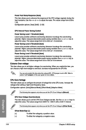
... the response of the CPU voltage regulator during the load transients. Use the or keys to adjust the value, The values range from 0.00 to [Manual]. Extreme Over-voltage This item allows you set the CPU Core Voltage to 1.50. The values range from 0 A to adjust the value. Configuration options: [Auto...
... the response of the CPU voltage regulator during the load transients. Use the or keys to adjust the value, The values range from 0.00 to [Manual]. Extreme Over-voltage This item allows you set the CPU Core Voltage to 1.50. The values range from 0 A to adjust the value. Configuration options: [Auto...

User Guide
Page 132
.... Visit http://www.asus.com to download the latest BIOS file for more information. ASUS BIOS Updater: Updates the BIOS in DOS environment using the current version of this user guide for this chapter to section 4.4.3 EZ Update of BIOS, DO NOT manually update the BIOS. ... through a network or an ISP (Internet Service Provider). • This utility is potentially risky. 3.11 Updating BIOS The ASUS website publishes the latest BIOS versions to boot. ASUS CrashFree BIOS 3: Restores the BIOS using a USB flash drive. 3. Chapter 3 3-60 Chapter 3: BIOS setup The following...
.... Visit http://www.asus.com to download the latest BIOS file for more information. ASUS BIOS Updater: Updates the BIOS in DOS environment using the current version of this user guide for this chapter to section 4.4.3 EZ Update of BIOS, DO NOT manually update the BIOS. ... through a network or an ISP (Internet Service Provider). • This utility is potentially risky. 3.11 Updating BIOS The ASUS website publishes the latest BIOS versions to boot. ASUS CrashFree BIOS 3: Restores the BIOS using a USB flash drive. 3. Chapter 3 3-60 Chapter 3: BIOS setup The following...

User Guide
Page 140
Click or tap an icon to display the ASUS contact information. The Manual menu contains the list of the user guide. The AHCI/RAID Driver menu contains the RAID/AHCI driver disk. The Utilities menu shows the applications and other software that the motherboard supports. ... item to install Click or tap to display DVD/motherboard information Chapter 4 4-2 Chapter 4: Software support Install the necessary drivers to open the folder of supplementary user guides.
Click or tap an icon to display the ASUS contact information. The Manual menu contains the list of the user guide. The AHCI/RAID Driver menu contains the RAID/AHCI driver disk. The Utilities menu shows the applications and other software that the motherboard supports. ... item to install Click or tap to display DVD/motherboard information Chapter 4 4-2 Chapter 4: Software support Install the necessary drivers to open the folder of supplementary user guides.

User Guide
Page 144
Click or tap to launch AI Suite 3 menu bar The Ai Suite 3 screenshots in this user guide may vary depending on the motherboard model. • Refer to the software manual in this section are for detailed software configuration. 4-6 Chapter 4: Software support Chapter 4 AI Suite 3 Main menu The AI Suite 3 ... Boost System USB Charger+ Push Notice Information • Some functions in the AI Suite 3 main menu in the support DVD or visit the ASUS website at the same time ensuring system stability. The AI Suite main menu includes is a quick-access menu bar that allows you easy-access...
Click or tap to launch AI Suite 3 menu bar The Ai Suite 3 screenshots in this user guide may vary depending on the motherboard model. • Refer to the software manual in this section are for detailed software configuration. 4-6 Chapter 4: Software support Chapter 4 AI Suite 3 Main menu The AI Suite 3 ... Boost System USB Charger+ Push Notice Information • Some functions in the AI Suite 3 main menu in the support DVD or visit the ASUS website at the same time ensuring system stability. The AI Suite main menu includes is a quick-access menu bar that allows you easy-access...

User Guide
Page 170
... graphics cards and the motherboard layout may vary with graphics cards) Goldfingers Chapter 6 6-2 Chapter 6: Multiple GPU support Ensure that the connector is firmly in this user manual for the locations of the PCIEX16 slots recommended for reference only. If your motherboard has more than two PCIEX16 slots, refer to the goldfingers on...
... graphics cards and the motherboard layout may vary with graphics cards) Goldfingers Chapter 6 6-2 Chapter 6: Multiple GPU support Ensure that the connector is firmly in this user manual for the locations of the PCIEX16 slots recommended for reference only. If your motherboard has more than two PCIEX16 slots, refer to the goldfingers on...

User Guide
Page 171
... supply to Chapter 1 in place. 5. Insert the three graphics card into the PCIEX16 slots. Ensure that the cards are firmly in this user manual for the locations of the PCIEX16 slots recommended for multi-graphics card installation. 3. Connect a VGA or a DVI cable to the graphics card...the power supply to the goldfingers on the slots. 4. 5. Ensure that the connectors are properly seated on each graphics card. Chapter 6 Z97-WS 6-3 Connect a VGA or a DVI cable to the graphics card. Align and firmly insert the two CrossFireX bridge connectors to the two graphics cards...
... supply to Chapter 1 in place. 5. Insert the three graphics card into the PCIEX16 slots. Ensure that the cards are firmly in this user manual for the locations of the PCIEX16 slots recommended for multi-graphics card installation. 3. Connect a VGA or a DVI cable to the graphics card...the power supply to the goldfingers on the slots. 4. 5. Ensure that the connectors are properly seated on each graphics card. Chapter 6 Z97-WS 6-3 Connect a VGA or a DVI cable to the graphics card. Align and firmly insert the two CrossFireX bridge connectors to the two graphics cards...

User Guide
Page 172
... three CrossFireX bridge connectors to Chapter 1 in place. 5. Insert the four graphics cards into the PCIEX16 slots. Ensure that the cards are firmly in this user manual for the locations of the PCIEX16 slots recommended for multi-graphics card installation. 3. Chapter 6 6-4 Chapter 6: Multiple GPU support 6.1.5 Installing four CrossFireX™ graphics cards...
... three CrossFireX bridge connectors to Chapter 1 in place. 5. Insert the four graphics cards into the PCIEX16 slots. Ensure that the cards are firmly in this user manual for the locations of the PCIEX16 slots recommended for multi-graphics card installation. 3. Chapter 6 6-4 Chapter 6: Multiple GPU support 6.1.5 Installing four CrossFireX™ graphics cards...
User Guide
Page 175
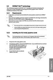
.... 1. If your motherboard has more than two PCIEX16 slots, refer to install multi-graphics processing units (GPU) graphics cards. Chapter 6 Z97-WS 6-7 Prepare two SLI-ready graphics cards. 2. Ensure that the cards are for multigraphics card installation. 3. Download the latest driver from the... cards that are NVIDIA® certified. • Ensure that your system. • We recommend that you to Chapter 1 in this user manual for the locations of the PCIEX16 slots recommended for reference only. 6.2 NVIDIA® SLI™ technology The motherboard supports the NVIDIA®...
.... 1. If your motherboard has more than two PCIEX16 slots, refer to install multi-graphics processing units (GPU) graphics cards. Chapter 6 Z97-WS 6-7 Prepare two SLI-ready graphics cards. 2. Ensure that the cards are for multigraphics card installation. 3. Download the latest driver from the... cards that are NVIDIA® certified. • Ensure that your system. • We recommend that you to Chapter 1 in this user manual for the locations of the PCIEX16 slots recommended for reference only. 6.2 NVIDIA® SLI™ technology The motherboard supports the NVIDIA®...

User Guide
Page 176
... 1 in place. 5. Chapter 6 6-8 Chapter 6: Multiple GPU support If your graphics card package to install the device drivers. 1. Ensure that the connector is firmly in this user manual for locations of the PCIEX16 slots recommended for multi-graphics card installation. 3. Connect a VGA or a DVI cable to the goldfingers on the slots. Insert the...
... 1 in place. 5. Chapter 6 6-8 Chapter 6: Multiple GPU support If your graphics card package to install the device drivers. 1. Ensure that the connector is firmly in this user manual for locations of the PCIEX16 slots recommended for multi-graphics card installation. 3. Connect a VGA or a DVI cable to the goldfingers on the slots. Insert the...

User Guide
Page 177
... to the three graphics cards separately. 6. Ensure that the connector is firmly in place. 3-way SLI bridge 5. Chapter 6 4-way SLI bridge Z97-WS 6-9 Ensure that the connector is firmly in this user manual for the locations of the PCIEX16 slots recommended for multi-graphics card installation. 3. Connect a VGA or a DVI cable to the graphics...
... to the three graphics cards separately. 6. Ensure that the connector is firmly in place. 3-way SLI bridge 5. Chapter 6 4-way SLI bridge Z97-WS 6-9 Ensure that the connector is firmly in this user manual for the locations of the PCIEX16 slots recommended for multi-graphics card installation. 3. Connect a VGA or a DVI cable to the graphics...
