
User Manual
Page 1
Motherboard Z8PE-D12 Series Z8PE-D12X Z8PE-D12
Motherboard Z8PE-D12 Series Z8PE-D12X Z8PE-D12
User Manual
Page 3
... Notices...vii Safety information viii About this guide ix Typography x Z8PE-D12 Series specifications summary xi Chapter 1: Product introduction 1.1 Welcome 1-3 1.2 Package contents 1-3 1.3 Serial number label 1-4 1.4 Special features 1-4 1.4.1 Product highlights 1-4 1.4.2 Innovative ASUS features 1-6 Chapter 2: Hardware information 2.1 Before you proceed 2-3 2.2 Motherboard overview 2-6 2.2.1 Placement direction 2-6 2.2.2 Screw holes 2-6 2.2.3 Motherboard layouts 2-7 2.2.4 Layout contents 2-9 2.3 Central Processing Unit (CPU 2-11 2.3.1 Installing the...
... Notices...vii Safety information viii About this guide ix Typography x Z8PE-D12 Series specifications summary xi Chapter 1: Product introduction 1.1 Welcome 1-3 1.2 Package contents 1-3 1.3 Serial number label 1-4 1.4 Special features 1-4 1.4.1 Product highlights 1-4 1.4.2 Innovative ASUS features 1-6 Chapter 2: Hardware information 2.1 Before you proceed 2-3 2.2 Motherboard overview 2-6 2.2.1 Placement direction 2-6 2.2.2 Screw holes 2-6 2.2.3 Motherboard layouts 2-7 2.2.4 Layout contents 2-9 2.3 Central Processing Unit (CPU 2-11 2.3.1 Installing the...
User Manual
Page 8
...where it may become wet. • Place the product on it by yourself. This symbol of electronic products. Operation safety • Before installing the motherboard and adding devices on a stable surface. • If you add a device. • Before connecting or removing signal cables from the... motherboard, ensure that the power cables for disposal of the crossed out wheeled bin indicates that your dealer immediately. • To avoid short circuits, keep...
...where it may become wet. • Place the product on it by yourself. This symbol of electronic products. Operation safety • Before installing the motherboard and adding devices on a stable surface. • If you add a device. • Before connecting or removing signal cables from the... motherboard, ensure that the power cables for disposal of the crossed out wheeled bin indicates that your dealer immediately. • To avoid short circuits, keep...
User Manual
Page 9
...lists the hardware setup procedures that may have to when configuring the motherboard. ix Detailed descriptions of the BIOS parameters are not part of the switches, jumpers, and connectors on ASUS hardware and software products. Optional documentation Your product package may include... of shutting down the system. • Chapter 4: BIOS setup This chapter tells how to the ASUS contact information. 2. ASUS websites The ASUS website provides updated information on the motherboard. • Chapter 3: Powering up This chapter describes the power up , creating, and configuring RAID...
...lists the hardware setup procedures that may have to when configuring the motherboard. ix Detailed descriptions of the BIOS parameters are not part of the switches, jumpers, and connectors on ASUS hardware and software products. Optional documentation Your product package may include... of shutting down the system. • Chapter 4: BIOS setup This chapter tells how to the ASUS contact information. 2. ASUS websites The ASUS website provides updated information on the motherboard. • Chapter 3: Powering up This chapter describes the power up , creating, and configuring RAID...

User Manual
Page 15
This chapter describes the motherboard introPdruoc1dtuiocnt features and the new technologies it supports.
This chapter describes the motherboard introPdruoc1dtuiocnt features and the new technologies it supports.
User Manual
Page 17
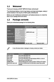
... damaged or missing, contact your motherboard package for buying an ASUS® Z8PE-D12 Series motherboard! Cables IDE cable 1 -- Thank you start installing the motherboard, and hardware devices on it ...Z8PE-D12 series Z8PE-D12 series SATA data cable 6 -- Discrete 8 channel audio card provides clearest high quality sounds ASUS Z8PE-D12 Series 1-3 Accessories IO shield 1 1 Support CD 1 1 Application CD CA eTrust Anti-virus software CD 1 1 Documentation User Guide 1 1 Packing Qty. 1pcs per carton 10pcs per carton If any of ASUS quality motherboards...
... damaged or missing, contact your motherboard package for buying an ASUS® Z8PE-D12 Series motherboard! Cables IDE cable 1 -- Thank you start installing the motherboard, and hardware devices on it ...Z8PE-D12 series Z8PE-D12 series SATA data cable 6 -- Discrete 8 channel audio card provides clearest high quality sounds ASUS Z8PE-D12 Series 1-3 Accessories IO shield 1 1 Support CD 1 1 Application CD CA eTrust Anti-virus software CD 1 1 Documentation User Guide 1 1 Packing Qty. 1pcs per carton 10pcs per carton If any of ASUS quality motherboards...
User Manual
Page 18
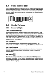
...as long as the figure below. The Intel® EM64T feature allows your problems. Z8PE-D12 xxM0Axxxxxxx Made in China 合格 1.4 Special features 1.4.1 Product highlights Latest processor technology This motherboard supports the latest Intel Xeon 5500 series processors in the world. Intel Xeon 5500 ...and a max bandwidth of up to 25.6GB/s. 1.3 Serial number label Before requesting support from the ASUS Technical Support team, you must take note of the motherboard's serial number containing 12 characters xxM0Axxxxxxx shown as the CPU temperature is the one of the most powerful...
...as long as the figure below. The Intel® EM64T feature allows your problems. Z8PE-D12 xxM0Axxxxxxx Made in China 合格 1.4 Special features 1.4.1 Product highlights Latest processor technology This motherboard supports the latest Intel Xeon 5500 series processors in the world. Intel Xeon 5500 ...and a max bandwidth of up to 25.6GB/s. 1.3 Serial number label Before requesting support from the ASUS Technical Support team, you must take note of the motherboard's serial number containing 12 characters xxM0Axxxxxxx shown as the CPU temperature is the one of the most powerful...
User Manual
Page 19
...voltage monitoring The CPU temperature is backward compatible with lower pin count and reduced voltage requirements. Serial ATA II technology The motherboard supports the Serial ATA II 3 Gb/s technology through the Serial ATA interface and Intel ICH10R chipset. The 3-channel ... and ports which makes it an ideal memory solution. USB 2.0 technology The motherboard implements the Universal Serial Bus (USB) 2.0 specification, dramatically increasing the connection speed from 1.8 V for DDR3. The chip monitors the voltage levels to Gigabit bandwidth. ASUS Z8PE-D12 Series 1-5
...voltage monitoring The CPU temperature is backward compatible with lower pin count and reduced voltage requirements. Serial ATA II technology The motherboard supports the Serial ATA II 3 Gb/s technology through the Serial ATA interface and Intel ICH10R chipset. The 3-channel ... and ports which makes it an ideal memory solution. USB 2.0 technology The motherboard implements the Universal Serial Bus (USB) 2.0 specification, dramatically increasing the connection speed from 1.8 V for DDR3. The chip monitors the voltage levels to Gigabit bandwidth. ASUS Z8PE-D12 Series 1-5
User Manual
Page 20
... users. 100% Japan-made Conductive Polymer Capacitors This motherboard uses all high-quality conductive polymer capacitors (5000hrs) onboard for durability, improved lifespan, and enhanced thermal capacity. 1.4.2 Innovative ASUS features ASUS EPU With current trends leaning towards power efficiency, the Z8PE-D12X is equipped with the ASUS exclusive EPU technology to provide total system power saving...
... users. 100% Japan-made Conductive Polymer Capacitors This motherboard uses all high-quality conductive polymer capacitors (5000hrs) onboard for durability, improved lifespan, and enhanced thermal capacity. 1.4.2 Innovative ASUS features ASUS EPU With current trends leaning towards power efficiency, the Z8PE-D12X is equipped with the ASUS exclusive EPU technology to provide total system power saving...

User Manual
Page 21
It includes description of the jumpers and connectors on the motherboard. 2 Hardware information This chapter lists the hardware setup procedures that you have to perform when installing system components.
It includes description of the jumpers and connectors on the motherboard. 2 Hardware information This chapter lists the hardware setup procedures that you have to perform when installing system components.
User Manual
Page 22
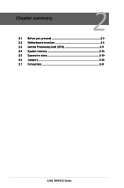
Chapter summary 2 2.1 Before you proceed 2-3 2.2 Motherboard overview 2-6 2.3 Central Processing Unit (CPU 2-11 2.4 System memory 2-16 2.5 Expansion slots 2-19 2.6 Jumpers 2-25 2.7 Connectors 2-31 ASUS Z8PE-D12 Series
Chapter summary 2 2.1 Before you proceed 2-3 2.2 Motherboard overview 2-6 2.3 Central Processing Unit (CPU 2-11 2.4 System memory 2-16 2.5 Expansion slots 2-19 2.6 Jumpers 2-25 2.7 Connectors 2-31 ASUS Z8PE-D12 Series
User Manual
Page 23
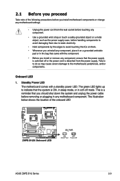
.... • Unplug the power cord from the power supply. Onboard LED 1. Standby Power LED The motherboard comes with the component. • Before you install or remove any motherboard component. The green LED lights up to the motherboard, peripherals, and/or components. Failure to do so may cause severe damage to indicate that the..., place it on a grounded antistatic pad or in the bag that came with a standby power LED. 2.1 Before you proceed Take note of the onboard LED ASUS Z8PE-D12 Series 2-3
.... • Unplug the power cord from the power supply. Onboard LED 1. Standby Power LED The motherboard comes with the component. • Before you install or remove any motherboard component. The green LED lights up to the motherboard, peripherals, and/or components. Failure to do so may cause severe damage to indicate that the..., place it on a grounded antistatic pad or in the bag that came with a standby power LED. 2.1 Before you proceed Take note of the onboard LED ASUS Z8PE-D12 Series 2-3
User Manual
Page 26
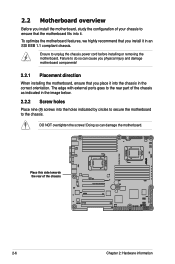
...the chassis power cord before installing or removing the motherboard. The edge with external ports goes to the rear part of the chassis as indicated in an SSI EEB 1.1 compliant chassis. Failure to do so can damage the motherboard. Place this side towards the rear of the... chassis 2-6 Chapter 2: Hardware information 2.2 Motherboard overview Before you install the motherboard, study the configuration of your chassis to...
...the chassis power cord before installing or removing the motherboard. The edge with external ports goes to the rear part of the chassis as indicated in an SSI EEB 1.1 compliant chassis. Failure to do so can damage the motherboard. Place this side towards the rear of the... chassis 2-6 Chapter 2: Hardware information 2.2 Motherboard overview Before you install the motherboard, study the configuration of your chassis to...
User Manual
Page 27
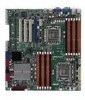
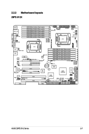
2.2.3 Motherboard layouts Z8PE-D12X ASUS Z8PE-D12 Series 2-7
2.2.3 Motherboard layouts Z8PE-D12X ASUS Z8PE-D12 Series 2-7
User Manual
Page 31
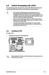
... cap/socket contacts/motherboard components. ASUS Z8PE-D12 Series 2-11 Before installing the CPU, ensure that the PnP cap is shipment/transit-related. • Keep the cap after installing the motherboard. ASUS will process Return Merchandise Authorization (RMA) requests only if the motherboard comes with dual ... of the PnP cap. 2.3.1 Installing the CPU To install a CPU: 1. 2.3 Central Processing Unit (CPU) The motherboard comes with the cap on the motherboard. ASUS shoulders the repair cost only if the damage is on your retailer immediately if the PnP cap is missing, or if...
... cap/socket contacts/motherboard components. ASUS Z8PE-D12 Series 2-11 Before installing the CPU, ensure that the PnP cap is shipment/transit-related. • Keep the cap after installing the motherboard. ASUS will process Return Merchandise Authorization (RMA) requests only if the motherboard comes with dual ... of the PnP cap. 2.3.1 Installing the CPU To install a CPU: 1. 2.3 Central Processing Unit (CPU) The motherboard comes with the cap on the motherboard. ASUS shoulders the repair cost only if the damage is on your retailer immediately if the PnP cap is missing, or if...
User Manual
Page 36
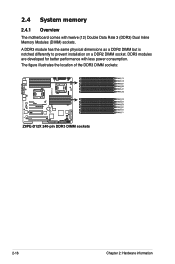
The figure illustrates the location of the DDR3 DIMM sockets: 2-16 Chapter 2: Hardware information 2.4 System memory 2.4.1 Overview The motherboard comes with less power consumption. DDR3 modules are developed for better performance with twelve (12) Double Data Rate 3 (DDR3) Dual Inline Memory Modules (DIMM) sockets. A DDR3 module has the same physical dimensions as a DDR2 DIMM but is notched differently to prevent installation on a DDR2 DIMM socket.
The figure illustrates the location of the DDR3 DIMM sockets: 2-16 Chapter 2: Hardware information 2.4 System memory 2.4.1 Overview The motherboard comes with less power consumption. DDR3 modules are developed for better performance with twelve (12) Double Data Rate 3 (DDR3) Dual Inline Memory Modules (DIMM) sockets. A DDR3 module has the same physical dimensions as a DDR2 DIMM but is notched differently to prevent installation on a DDR2 DIMM socket.
User Manual
Page 38
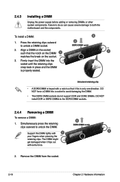
Unlocked retaining clip • A DDR3 DIMM is properly seated. Simultaneously press the retaining clips outward to both the motherboard and the components. DO NOT force a DIMM into the socket until the retaining clips snap back in place and the DIMM is keyed with a notch ...
Unlocked retaining clip • A DDR3 DIMM is properly seated. Simultaneously press the retaining clips outward to both the motherboard and the components. DO NOT force a DIMM into the socket until the retaining clips snap back in place and the DIMM is keyed with a notch ...
User Manual
Page 39
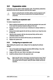
Remove the system unit cover (if your motherboard is completely seated on the slot. 5. Install the software drivers for information on the system and change the necessary BIOS settings, if any. ASUS Z8PE-D12 Series 2-19 Before installing the expansion card, read the documentation that you...power cord before adding or removing expansion cards. 2.5 Expansion slots In the future, you may cause you physical injury and damage motherboard components. 2.5.1 Installing an expansion card To install an expansion card: 1. The following subsections describe the slots and the expansion ...
Remove the system unit cover (if your motherboard is completely seated on the slot. 5. Install the software drivers for information on the system and change the necessary BIOS settings, if any. ASUS Z8PE-D12 Series 2-19 Before installing the expansion card, read the documentation that you...power cord before adding or removing expansion cards. 2.5 Expansion slots In the future, you may cause you physical injury and damage motherboard components. 2.5.1 Installing an expansion card To install an expansion card: 1. The following subsections describe the slots and the expansion ...
User Manual
Page 42
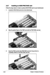
Locate the PIKE RAID card slot on the PIKE RAID card slot. 2-22 Chapter 2: Hardware information Ensure that it is completely seated on the motherboard. 2. 2.5.7 Installing an ASUS PIKE RAID card Follow the steps below to install an optional ASUS RAID card on your motherboard. 1. Align the golden fingers of the RAID card with the PIKE RAID card slot. 3. Insert the RAID card into the PIKE RAID card slot.
Locate the PIKE RAID card slot on the PIKE RAID card slot. 2-22 Chapter 2: Hardware information Ensure that it is completely seated on the motherboard. 2. 2.5.7 Installing an ASUS PIKE RAID card Follow the steps below to install an optional ASUS RAID card on your motherboard. 1. Align the golden fingers of the RAID card with the PIKE RAID card slot. 3. Insert the RAID card into the PIKE RAID card slot.

User Manual
Page 43
ASUS Z8PE-D12 Series 2-23 You need to install I Button before using PIKE 1078 functions. 2.5.9 Installing ASMB4 management board Follow the steps below to install an optional i Button on your motherboard. 1. Locate the BMC_FW header on the motherboard. 2. Snap the I Button slot on the motherboard. 2. You need to install I Button before using PIKE 1078 functions. Locate the...
ASUS Z8PE-D12 Series 2-23 You need to install I Button before using PIKE 1078 functions. 2.5.9 Installing ASMB4 management board Follow the steps below to install an optional i Button on your motherboard. 1. Locate the BMC_FW header on the motherboard. 2. Snap the I Button slot on the motherboard. 2. You need to install I Button before using PIKE 1078 functions. Locate the...


