User Manual
Page 3
...guide ix Typography x Z8PE-D12 Series specifications summary xi Chapter 1: Product introduction 1.1 Welcome 1-3 1.2 Package contents 1-3 1.3 Serial number label 1-4 1.4 Special features 1-4 1.4.1 Product highlights 1-4 1.4.2 Innovative ASUS features 1-6 Chapter 2: Hardware information 2.1 Before you proceed 2-3 2.2 Motherboard overview 2-6 2.2.1 Placement direction 2-6 2.2.2 Screw holes 2-6 2.2.3 Motherboard layouts 2-7 2.2.4 Layout contents 2-9 2.3 Central Processing Unit (CPU 2-11 2.3.1 Installing the CPU 2-11 2.3.2 Installing the CPU heatsink and fan 2-14 2.4 System memory...
...guide ix Typography x Z8PE-D12 Series specifications summary xi Chapter 1: Product introduction 1.1 Welcome 1-3 1.2 Package contents 1-3 1.3 Serial number label 1-4 1.4 Special features 1-4 1.4.1 Product highlights 1-4 1.4.2 Innovative ASUS features 1-6 Chapter 2: Hardware information 2.1 Before you proceed 2-3 2.2 Motherboard overview 2-6 2.2.1 Placement direction 2-6 2.2.2 Screw holes 2-6 2.2.3 Motherboard layouts 2-7 2.2.4 Layout contents 2-9 2.3 Central Processing Unit (CPU 2-11 2.3.1 Installing the CPU 2-11 2.3.2 Installing the CPU heatsink and fan 2-14 2.4 System memory...
User Manual
Page 13
...is available only when you install ASUS PIKE 1078 RAID card with iBTN. • The onboard IDE connector is designed for ODD only (PATA). xiii DO NOT touch the Northbridge chipset! The Northbridge chipset may become overheated. Z8PE-D12 Series specifications summary Onboard I/O ...1 Software ASWM ASWM Out of Band Remote Management Optional ASMB4-iKVM for Optional ASMB4-iKVM for KVM-over-IP support KVM-over-IP support CPU V V Temperature FAN RPM V V Operation temperature: Operation temperature: 10℃ ~ 35℃ 10℃ ~ 35℃ Non operation temperature: Non ...
...is available only when you install ASUS PIKE 1078 RAID card with iBTN. • The onboard IDE connector is designed for ODD only (PATA). xiii DO NOT touch the Northbridge chipset! The Northbridge chipset may become overheated. Z8PE-D12 Series specifications summary Onboard I/O ...1 Software ASWM ASWM Out of Band Remote Management Optional ASMB4-iKVM for Optional ASMB4-iKVM for KVM-over-IP support KVM-over-IP support CPU V V Temperature FAN RPM V V Operation temperature: Operation temperature: 10℃ ~ 35℃ 10℃ ~ 35℃ Non operation temperature: Non ...
User Manual
Page 19
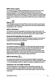
...1.8 V for DDR2 to PCIe 1.0 devices. 82574L LAN Solution The motherboard comes with dual Gigabit LAN controllers and ports which makes it an ideal memory solution. Temperature, fan, and voltage monitoring The CPU temperature is monitored for timely failure detection. The 3-channel DDR3 architecture ...of 1333/1066 MHZ to meet the higher bandwidth requirements of DDR3 which provide a total solution for your networking needs. ASUS Z8PE-D12 Series 1-5 This voltage reduction limits the power consumption and heat generation of server and workstation applications. Serial ATA allows thinner...
...1.8 V for DDR2 to PCIe 1.0 devices. 82574L LAN Solution The motherboard comes with dual Gigabit LAN controllers and ports which makes it an ideal memory solution. Temperature, fan, and voltage monitoring The CPU temperature is monitored for timely failure detection. The 3-channel DDR3 architecture ...of 1333/1066 MHZ to meet the higher bandwidth requirements of DDR3 which provide a total solution for your networking needs. ASUS Z8PE-D12 Series 1-5 This voltage reduction limits the power consumption and heat generation of server and workstation applications. Serial ATA allows thinner...
User Manual
Page 29
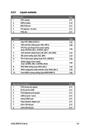
...3. CPU Fan and Chassis Fan control setting (3-pin CPUFAN_SEL1, CHAFAN_SEL1) 4. LAN controller setting (3-pin LAN_SW1, LAN_SW2) 5. RJ-45 port for iKVM 3. LAN 2 (RJ-45) port Page 2-11 2-16 2-21 2-21 2-21 Page 2-25 2-26 2-26 2-27 2-27 2-28 2-28 2-29 2-29 2-30 Page 2-31 2-31 2-31 2-31 2-31 2-31 2-31 2-31 ASUS Z8PE-D12 Series... setting (4-pin LVDDR3_SEL1; RAID configuration utility selection (3-pin RAID_SEL1) 10. IDE control setting (3-pin IDE_SW1) 6. PIKE slot Jumpers 1. LVDDR3_SEL2) 8. 2.2.4 Layout contents Slots/Soocket 1. CPU sockets 2. PCI Express x 16 slots 5.
...3. CPU Fan and Chassis Fan control setting (3-pin CPUFAN_SEL1, CHAFAN_SEL1) 4. LAN controller setting (3-pin LAN_SW1, LAN_SW2) 5. RJ-45 port for iKVM 3. LAN 2 (RJ-45) port Page 2-11 2-16 2-21 2-21 2-21 Page 2-25 2-26 2-26 2-27 2-27 2-28 2-28 2-29 2-29 2-30 Page 2-31 2-31 2-31 2-31 2-31 2-31 2-31 2-31 ASUS Z8PE-D12 Series... setting (4-pin LVDDR3_SEL1; RAID configuration utility selection (3-pin RAID_SEL1) 10. IDE control setting (3-pin IDE_SW1) 6. PIKE slot Jumpers 1. LVDDR3_SEL2) 8. 2.2.4 Layout contents Slots/Soocket 1. CPU sockets 2. PCI Express x 16 slots 5.

User Manual
Page 34
... heatsink screws in a diagonal sequence. Ensure that the screw holes are matched with the heatsink standoffs. 2. Use a Phillips screwdriver to install the CPU heatsink and fan. 1. 2.3.2 Installing the CPU heatsink and fan The Intel Xeon 5500 series processors require a specially designed heatsink to ensure optimum thermal condition and performance. • Ensure to use qualified...
... heatsink screws in a diagonal sequence. Ensure that the screw holes are matched with the heatsink standoffs. 2. Use a Phillips screwdriver to install the CPU heatsink and fan. 1. 2.3.2 Installing the CPU heatsink and fan The Intel Xeon 5500 series processors require a specially designed heatsink to ensure optimum thermal condition and performance. • Ensure to use qualified...

User Manual
Page 35
ASUS Z8PE-D12 Series 2-15 3. Connect the fan cable to the 4‑pin connector labeled CPU_FAN1 or CPU_FAN2 depending on the CPU socket you install. 3. ���R��e�p�e��a�t�s�t�e�p��s�1��t�o&#...65533;v�e��i�n�s�t�a�l�le�d��a��s�e��c�o�n�d� CPU, then connect the fan cable to the other 4‑pin connector.
ASUS Z8PE-D12 Series 2-15 3. Connect the fan cable to the 4‑pin connector labeled CPU_FAN1 or CPU_FAN2 depending on the CPU socket you install. 3. ���R��e�p�e��a�t�s�t�e�p��s�1��t�o&#...65533;v�e��i�n�s�t�a�l�le�d��a��s�e��c�o�n�d� CPU, then connect the fan cable to the other 4‑pin connector.
User Manual
Page 46
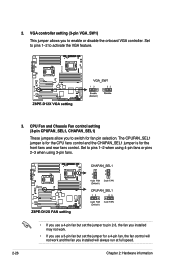
... run at full speed. 2-26 Chapter 2: Hardware information Set to pins 1-2 when using 4-pin fans or pins 2-3 when using 3-pin fans. • If you use a 4-pin fan but set the jumper to enable or disable the onboard VGA controller. CPU Fan and Chassis Fan control setting (3-pin CPUFAN_SEL1, CHAFAN_SEL1) These jumpers allow you to pin 2-3, the...
... run at full speed. 2-26 Chapter 2: Hardware information Set to pins 1-2 when using 4-pin fans or pins 2-3 when using 3-pin fans. • If you use a 4-pin fan but set the jumper to enable or disable the onboard VGA controller. CPU Fan and Chassis Fan control setting (3-pin CPUFAN_SEL1, CHAFAN_SEL1) These jumpers allow you to pin 2-3, the...

User Manual
Page 56
DO NOT place jumper caps on the motherboard, ensuring that the black wire of each cable matches the ground pin of 3.15 A-6.66 A (53.28 W max.) at +12V. Connect the fan cables to the fan connectors on the fan connectors! • All fans feature the ASUS Smart Fan technology. 9. 8. CPU, front and rear fan connectors (4-pin CPU_FAN1, CPU_FAN2, FRNT_FAN1, FRNT_FAN2...
DO NOT place jumper caps on the motherboard, ensuring that the black wire of each cable matches the ground pin of 3.15 A-6.66 A (53.28 W max.) at +12V. Connect the fan cables to the fan connectors on the fan connectors! • All fans feature the ASUS Smart Fan technology. 9. 8. CPU, front and rear fan connectors (4-pin CPU_FAN1, CPU_FAN2, FRNT_FAN1, FRNT_FAN2...

User Manual
Page 94
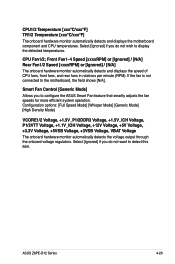
...Monitor CPU1 Temperature CPU2 Temperature TR1 Temperature TR2 Temperature CPU Fan1 Speed CPU Fan2 Speed Front Fan1 Speed Front Fan2 Speed Front Fan3 Speed ...Fan Control VCORE1 Voltage VCORE2 Voltage +1.5V_P1DDR3 Voltage +1.5V_P2DDR3 Voltage +1.5V_ICH Voltage [ 27.5ºC/ 81.5ºF] [ 0 ºC/ 32 ºF] [ N/A ] [ N/A ] [ N/A ] [ N/A ] [ N/A ] [ N/A ] [ N/A ] [ N/A ] [ N/A ] [ N/A ] [Generic Mode] [ 1.052 V] [ N/A ] [ 1.508 V] [ N/A ] [ 1.520 V] CPU1 Temperature +F1 F10 ESC Select Screen Select Item Change Option General Help Save and Exit Exit v02.61...
...Monitor CPU1 Temperature CPU2 Temperature TR1 Temperature TR2 Temperature CPU Fan1 Speed CPU Fan2 Speed Front Fan1 Speed Front Fan2 Speed Front Fan3 Speed ...Fan Control VCORE1 Voltage VCORE2 Voltage +1.5V_P1DDR3 Voltage +1.5V_P2DDR3 Voltage +1.5V_ICH Voltage [ 27.5ºC/ 81.5ºF] [ 0 ºC/ 32 ºF] [ N/A ] [ N/A ] [ N/A ] [ N/A ] [ N/A ] [ N/A ] [ N/A ] [ N/A ] [ N/A ] [ N/A ] [Generic Mode] [ 1.052 V] [ N/A ] [ 1.508 V] [ N/A ] [ 1.520 V] CPU1 Temperature +F1 F10 ESC Select Screen Select Item Change Option General Help Save and Exit Exit v02.61...
User Manual
Page 95
...ASUS Smart Fan feature that smartly adjusts the fan speeds for more efficient system operation. CPU Fan1/2; Smart Fan Control [Generic Mode] Allows you to the motherboard, the field shows [N/A]. Front Fan1-4 Speed [xxxxRPM] or [Ignored] / [N/A] Rear Fan1/2 Speed [xxxxRPM] or [Ignored] / [N/A] The onboard hardware monitor automatically detects and displays the speed of CPU fans, front fans, and rear fans... monitor automatically detects the voltage output through the onboard voltage regulators. ASUS Z8PE-D12 Series 4-29 Select [Ignored] if you do not wish to detect this item.
...ASUS Smart Fan feature that smartly adjusts the fan speeds for more efficient system operation. CPU Fan1/2; Smart Fan Control [Generic Mode] Allows you to the motherboard, the field shows [N/A]. Front Fan1-4 Speed [xxxxRPM] or [Ignored] / [N/A] Rear Fan1/2 Speed [xxxxRPM] or [Ignored] / [N/A] The onboard hardware monitor automatically detects and displays the speed of CPU fans, front fans, and rear fans... monitor automatically detects the voltage output through the onboard voltage regulators. ASUS Z8PE-D12 Series 4-29 Select [Ignored] if you do not wish to detect this item.


