
User Guide
Page 7
...If this equipment. Canadian Department of Chemicals) regulatory framework, we published the chemical substances in our products at ASUS REACH website at http://green.asus.com/english/REACH.htm. REACH Complying with the limits for help. The use of shielded cables for compliance ... between the equipment and receiver. • Connect the equipment to radio communications. This equipment generates, uses and can be determined by turning the equipment off and on, the user is required to assure compliance with manufacturer' s instructions, may cause undesired operation. This class...
...If this equipment. Canadian Department of Chemicals) regulatory framework, we published the chemical substances in our products at ASUS REACH website at http://green.asus.com/english/REACH.htm. REACH Complying with the limits for help. The use of shielded cables for compliance ... between the equipment and receiver. • Connect the equipment to radio communications. This equipment generates, uses and can be determined by turning the equipment off and on, the user is required to assure compliance with manufacturer' s instructions, may cause undesired operation. This class...
User Guide
Page 38
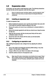
... IRQ assignments. Remove the bracket opposite the slot that they support. Ensure to the card. Remove the system unit cover (if your motherboard is completely seated on the system and change the necessary BIOS settings, if any. Install the software drivers for the card. 2. Assign.... Otherwise, conflicts will arise between the two PCI groups, making the system unstable and the card inoperable. 2-18 Chapter 2: Hardware information Turn on the slot. 5. The following subsections describe the slots and the expansion cards that you intend to the chassis with it by adjusting...
... IRQ assignments. Remove the bracket opposite the slot that they support. Ensure to the card. Remove the system unit cover (if your motherboard is completely seated on the system and change the necessary BIOS settings, if any. Install the software drivers for the card. 2. Assign.... Otherwise, conflicts will arise between the two PCI groups, making the system unstable and the card inoperable. 2-18 Chapter 2: Hardware information Turn on the slot. 5. The following subsections describe the slots and the expansion cards that you intend to the chassis with it by adjusting...

User Guide
Page 44
You can clear the CMOS memory of date, time, and system setup parameters by erasing the CMOS RTC RAM data. Plug the power cord and turn ON the computer. 4. After the CMOS clearance, reinstall the battery. 2-24 Chapter 2: Hardware information The onboard button cell battery powers the RAM data in... from pins 1-2 (default) to re-enter data. Keep the cap on CLRTC jumper default position. Removing the cap will cause system boot failure! Turn OFF the computer and unplug the power cord. 2. Hold down the key during the boot process and enter BIOS setup to pins 2-3. Except when ...
You can clear the CMOS memory of date, time, and system setup parameters by erasing the CMOS RTC RAM data. Plug the power cord and turn ON the computer. 4. After the CMOS clearance, reinstall the battery. 2-24 Chapter 2: Hardware information The onboard button cell battery powers the RAM data in... from pins 1-2 (default) to re-enter data. Keep the cap on CLRTC jumper default position. Removing the cap will cause system boot failure! Turn OFF the computer and unplug the power cord. 2. Hold down the key during the boot process and enter BIOS setup to pins 2-3. Except when ...
User Guide
Page 48
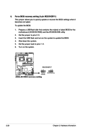
Prepare a USB flash disk that contains the original or latest BIOS for the motherboard (XXXXXX.ROM) and the AFUDOS.EXE utility. 2. Set the jumper back to pins 2-3. 3. 8. Set the jumper to pins 1-2. 6. Force BIOS recovery setting (3-pin RECOVERY1) This jumper allows you to update the BIOS. 4. Shut down the system. 5. Turn on the system to quickly update or recover the BIOS settings when it becomes corrupted. To update the BIOS: 1. Insert the USB flash and turn on the system. 2-28 Chapter 2: Hardware information
Prepare a USB flash disk that contains the original or latest BIOS for the motherboard (XXXXXX.ROM) and the AFUDOS.EXE utility. 2. Set the jumper back to pins 2-3. 3. 8. Set the jumper to pins 1-2. 6. Force BIOS recovery setting (3-pin RECOVERY1) This jumper allows you to update the BIOS. 4. Shut down the system. 5. Turn on the system to quickly update or recover the BIOS settings when it becomes corrupted. To update the BIOS: 1. Insert the USB flash and turn on the system. 2-28 Chapter 2: Hardware information

User Guide
Page 57
... lights up or flashes when data is for the message LED cable that connects to this connector. ASUS Z8NA-D6 Series 2-37 Pressing the power switch for the system power LED. System power LED (3-pin ...LED. Reset button (2-pin RESET) This 2-pin connector is for the chassis-mounted reset button for system reboot without turning off button (2-pin PWRSW) This connector is in sleep mode. 2. Hard disk drive activity LED (2-pin HDDLED) This...System panel connector (20-pin PANEL1) This connector supports several chassis-mounted functions. 1. ATX power button/soft-off the system power.
... lights up or flashes when data is for the message LED cable that connects to this connector. ASUS Z8NA-D6 Series 2-37 Pressing the power switch for the system power LED. System power LED (3-pin ...LED. Reset button (2-pin RESET) This 2-pin connector is for the chassis-mounted reset button for system reboot without turning off button (2-pin PWRSW) This connector is in sleep mode. 2. Hard disk drive activity LED (2-pin HDDLED) This...System panel connector (20-pin PANEL1) This connector supports several chassis-mounted functions. 1. ATX power button/soft-off the system power.

User Guide
Page 60
Chapter summary 3 3.1 Starting up for the first time 3-3 3.2 Turning off the computer 3-4 ASUS Z8NA-D6 Series
Chapter summary 3 3.1 Starting up for the first time 3-3 3.2 Turning off the computer 3-4 ASUS Z8NA-D6 Series

User Guide
Page 61
... monitor complies with ATX power supplies, the system LED lights up when you turned on the power, the system may light up or switch between orange and green after the system LED turns on the devices in Chapter 4. Turn on . While the tests are off. 3. Follow the instructions in the following order: a. ASUS Z8NA-D6 Series... chassis. 4. Connect the power cord to enter the BIOS Setup. If you do not see anything within 30 seconds from the time you press the ATX power button.
... monitor complies with ATX power supplies, the system LED lights up when you turned on the power, the system may light up or switch between orange and green after the system LED turns on the devices in Chapter 4. Turn on . While the tests are off. 3. Follow the instructions in the following order: a. ASUS Z8NA-D6 Series... chassis. 4. Connect the power cord to enter the BIOS Setup. If you do not see anything within 30 seconds from the time you press the ATX power button.

User Guide
Page 66
... CD to prevent system boot failure! 4-4 Chapter 4: BIOS setup Boot the system in DOS mode, then at www.asus.com and download the latest BIOS file for the motherboard. The utility copies the current BIOS file to type the exact BIOS filename at the DOS prompt. 2. You need...65533;�B��fl�a�s�h��d�i�s�k��d�r�iv��e��. Do not turn off power during flash BIOS Reading file ....... Press . done Write to file...... Updating the BIOS file To update the BIOS file using...
... CD to prevent system boot failure! 4-4 Chapter 4: BIOS setup Boot the system in DOS mode, then at www.asus.com and download the latest BIOS file for the motherboard. The utility copies the current BIOS file to type the exact BIOS filename at the DOS prompt. 2. You need...65533;�B��fl�a�s�h��d�i�s�k��d�r�iv��e��. Do not turn off power during flash BIOS Reading file ....... Press . done Write to file...... Updating the BIOS file To update the BIOS file using...

User Guide
Page 67
Version 1.19(ASUS V2.07(03.11.24BB)) Copyright (C) 2002 American Megatrends, Inc. done Reading flash ...... done Verifying flash .... Reboot the system from the hard disk drive. Do not turn off power during flash BIOS Reading file ....... A:\>afudos /i8036A0.ROM AMI Firmware Update Utility - Erasing flash ...... done Writing flash ...... WARNING!! 5. The utility returns to the DOS prompt after the BIOS update process is completed. done Advance Check ...... All rights reserved. done Please restart your computer A:\> ASUS Z8NA-D6 Series 4-5
Version 1.19(ASUS V2.07(03.11.24BB)) Copyright (C) 2002 American Megatrends, Inc. done Reading flash ...... done Verifying flash .... Reboot the system from the hard disk drive. Do not turn off power during flash BIOS Reading file ....... A:\>afudos /i8036A0.ROM AMI Firmware Update Utility - Erasing flash ...... done Writing flash ...... WARNING!! 5. The utility returns to the DOS prompt after the BIOS update process is completed. done Advance Check ...... All rights reserved. done Please restart your computer A:\> ASUS Z8NA-D6 Series 4-5

User Guide
Page 68
... floppy disk drive and turn the system. 2. Doing so would cause system boot failure! The recovered BIOS may not be the latest BIOS version for this utility. The utility will automatically recover the BIOS. Prepare a USB flash drive containing the updated motherboard BIOS before using a ...the latest BIOS file. 4-6 Chapter 4: BIOS setup Visit the ASUS website at www.asus.com to one USB port on the system. 3. It resets the system when the BIOS recovery finished. 4.1.2 ASUS CrashFree BIOS 3 utility The ASUS CrashFree BIOS 3 is an auto recovery tool that contains the updated...
... floppy disk drive and turn the system. 2. Doing so would cause system boot failure! The recovered BIOS may not be the latest BIOS version for this utility. The utility will automatically recover the BIOS. Prepare a USB flash drive containing the updated motherboard BIOS before using a ...the latest BIOS file. 4-6 Chapter 4: BIOS setup Visit the ASUS website at www.asus.com to one USB port on the system. 3. It resets the system when the BIOS recovery finished. 4.1.2 ASUS CrashFree BIOS 3 utility The ASUS CrashFree BIOS 3 is an auto recovery tool that contains the updated...

User Guide
Page 69
... computer in the future. If the system becomes unstable after POST, restart the system by pressing , or by turning the system off and then back on the motherboard stores the Setup utility. For example, you are not prompted to use as easy to make your selections from .... The LPC chip on . ASUS Z8NA-D6 Series 4-7 otherwise, POST continues with the opportunity to download the latest BIOS file for this program. Being a menu-driven program, it as possible. See section 4.8 Exit Menu. • The BIOS setup screens shown in this motherboard apply for reference purposes only, ...
... computer in the future. If the system becomes unstable after POST, restart the system by pressing , or by turning the system off and then back on the motherboard stores the Setup utility. For example, you are not prompted to use as easy to make your selections from .... The LPC chip on . ASUS Z8NA-D6 Series 4-7 otherwise, POST continues with the opportunity to download the latest BIOS file for this program. Being a menu-driven program, it as possible. See section 4.8 Exit Menu. • The BIOS setup screens shown in this motherboard apply for reference purposes only, ...

User Guide
Page 102
... option, a confirmation appears. Select YES to the non-volatile RAM. 4-40 Chapter 4: BIOS setup Select one of the parameters on even when the PC is turned off. 4.7 Exit menu The Exit menu items allow you to load the optimal or failsafe default values for the BIOS items, and save or discard...
... option, a confirmation appears. Select YES to the non-volatile RAM. 4-40 Chapter 4: BIOS setup Select one of the parameters on even when the PC is turned off. 4.7 Exit menu The Exit menu items allow you to load the optimal or failsafe default values for the BIOS items, and save or discard...
User Guide
Page 107
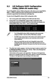
...motherboard southbridge chip. At the bottom of the screen is enabled. • The RAID setup screens shown in this section are for reference only and may not exactly match the items on the legend box vary according to Navigate Between Items And Press Enter To Select An Option ASUS Z8NA...-D6 Series 5-5 5.2 LSI Software RAID Configuration Utility (Z8NA-D6 model only) The LSI MegaRAID software RAID configuration utility allows you ... setup menu options or execute commands. Turn on the next page.
...motherboard southbridge chip. At the bottom of the screen is enabled. • The RAID setup screens shown in this section are for reference only and may not exactly match the items on the legend box vary according to Navigate Between Items And Press Enter To Select An Option ASUS Z8NA...-D6 Series 5-5 5.2 LSI Software RAID Configuration Utility (Z8NA-D6 model only) The LSI MegaRAID software RAID configuration utility allows you ... setup menu options or execute commands. Turn on the next page.

User Guide
Page 126
... Enable No Fast Init = Enable Auto Rebuild = On Auto Resume = Enable Disk Coercion = 1GB Factory Default Disk Write Cache - When finished, press any key to turn on the option. From the Management Menu, select Objects > Adapter, and then press to improve the data transmission performance. 5.2.8 Enabling WriteCache You may lose data...
... Enable No Fast Init = Enable Auto Rebuild = On Auto Resume = Enable Disk Coercion = 1GB Factory Default Disk Write Cache - When finished, press any key to turn on the option. From the Management Menu, select Objects > Adapter, and then press to improve the data transmission performance. 5.2.8 Enabling WriteCache You may lose data...

User Guide
Page 127
... disk drives that are for reference only and may not exactly match the items on the system. 3. Install all the Serial ATA hard disk drives. 2. Turn on your screen. Intel(R) Matrix Storage Manager option ROM v8.5.0.1030 ICH10R/DO wRAID5 Copyright(C) 2003-08 Intel Corporation. Recovery Volume Options RAID Volumes: None... [ESC]-Exit [ENTER]-Select Menu The navigation keys at the bottom of the screen allow you to the Serial ATA connectors supported by the Southbridge. ASUS Z8NA-D6 Series 5-25 Exit 3.
... disk drives that are for reference only and may not exactly match the items on the system. 3. Install all the Serial ATA hard disk drives. 2. Turn on your screen. Intel(R) Matrix Storage Manager option ROM v8.5.0.1030 ICH10R/DO wRAID5 Copyright(C) 2003-08 Intel Corporation. Recovery Volume Options RAID Volumes: None... [ESC]-Exit [ENTER]-Select Menu The navigation keys at the bottom of the screen allow you to the Serial ATA connectors supported by the Southbridge. ASUS Z8NA-D6 Series 5-25 Exit 3.


