
User Guide
Page 6
... Server OS 6-12 6.2 Intel chipset device software installation 6-15 6.3 LAN driver installation 6-19 6.4 Display driver installation 6-23 6.5 Management applications and utilitie installation 6-26 6.5.1 Running the support DVD 6-26 6.5.2 Drivers menu 6-26 6.5.3 Utilities menu 6-27 6.5.4 Make disk menu 6-27 6.5.5 Contact information 6-27 Appendix: Reference information A.1 Z8NA-D6 block diagram A-3 A.2 Z8NA-D6C block diagram A-4 vi
... Server OS 6-12 6.2 Intel chipset device software installation 6-15 6.3 LAN driver installation 6-19 6.4 Display driver installation 6-23 6.5 Management applications and utilitie installation 6-26 6.5.1 Running the support DVD 6-26 6.5.2 Drivers menu 6-26 6.5.3 Utilities menu 6-27 6.5.4 Make disk menu 6-27 6.5.5 Contact information 6-27 Appendix: Reference information A.1 Z8NA-D6 block diagram A-3 A.2 Z8NA-D6C block diagram A-4 vi
User Guide
Page 9
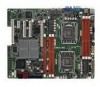
...the standard package. How this guide This user guide contains the information you may refer to the ASUS contact information. 2. ASUS websites The ASUS website provides updated information on the motherboard. • Chapter 3: Powering up This chapter describes the power up , creating, and configuring... Your product package may have been added by your dealer. Refer to when configuring the motherboard. ix Detailed descriptions of the motherboard and the new technologies it supports. • Chapter 2: Hardware information This chapter lists the hardware setup procedures that you have...
...the standard package. How this guide This user guide contains the information you may refer to the ASUS contact information. 2. ASUS websites The ASUS website provides updated information on the motherboard. • Chapter 3: Powering up This chapter describes the power up , creating, and configuring... Your product package may have been added by your dealer. Refer to when configuring the motherboard. ix Detailed descriptions of the motherboard and the new technologies it supports. • Chapter 2: Hardware information This chapter lists the hardware setup procedures that you have...
User Guide
Page 11
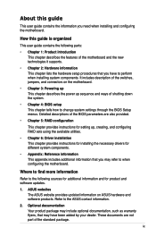
...Z8NA-D6 Z8NA-D6C Processor Support / System Bus 2 * socket 1366 Quad-Core Intel® Xeon® X5500 Series (95W) Quad-Core Intel® Xeon® E5500 Series (80W) Quad-Core Intel® Xeon® L5500 Series (60W/38W) Core Logic QPI 4.8 / 5.86 / 6.4 GT/s Intel® 5500 chipset I/O H Intel® ICH10R I/O Controller Form Factor ATX, 12" x 9.6" ASUS...Loacation #) Slot Loacation 1 * PCI 32bit/33 MHz 1 Slot Loacation 1* MIO Slot for Audio card (PCI-E x1 is not 2 supported) Slot Loacation 1 * PCI-E x8 (Gen2 X4 Link) 3 Slot Loacation 1 * PCI-E x8 (Gen2 X4 Link) 4 Slot ...
...Z8NA-D6 Z8NA-D6C Processor Support / System Bus 2 * socket 1366 Quad-Core Intel® Xeon® X5500 Series (95W) Quad-Core Intel® Xeon® E5500 Series (80W) Quad-Core Intel® Xeon® L5500 Series (60W/38W) Core Logic QPI 4.8 / 5.86 / 6.4 GT/s Intel® 5500 chipset I/O H Intel® ICH10R I/O Controller Form Factor ATX, 12" x 9.6" ASUS...Loacation #) Slot Loacation 1 * PCI 32bit/33 MHz 1 Slot Loacation 1* MIO Slot for Audio card (PCI-E x1 is not 2 supported) Slot Loacation 1 * PCI-E x8 (Gen2 X4 Link) 3 Slot Loacation 1 * PCI-E x8 (Gen2 X4 Link) 4 Slot ...
User Guide
Page 12
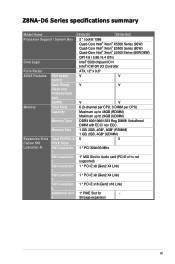
... RAID card; xii Asus PIKE 6480 8-port SAS RAID card 2 * Intel 82574L Aspeed AST2050 8MB 24-pin ATX power connector + 8-pin ATX 12V (Support Both ATX & SSI Power Supply)** Onboard header for KVM-over-Internet 1 2 1 ASWM - optional management card 2 (One for internal Type A USB connector) 8 * 4pin 2 2 1 1 2 2 1 1 1 1 2 2 1 2 1 ASWM Optional ASMB4-iKVM for - Z8NA-D6 Series specifications summary...
... RAID card; xii Asus PIKE 6480 8-port SAS RAID card 2 * Intel 82574L Aspeed AST2050 8MB 24-pin ATX power connector + 8-pin ATX 12V (Support Both ATX & SSI Power Supply)** Onboard header for KVM-over-Internet 1 2 1 ASWM - optional management card 2 (One for internal Type A USB connector) 8 * 4pin 2 2 1 1 2 2 1 1 1 1 2 2 1 2 1 ASWM Optional ASMB4-iKVM for - Z8NA-D6 Series specifications summary...

User Guide
Page 15
This chapter describes the motherboard introPdruoc1dtuiocnt features and the new technologies it supports.
This chapter describes the motherboard introPdruoc1dtuiocnt features and the new technologies it supports.

User Guide
Page 17
... SATA data cable Accessories IO shield Application CD Support CD Documentation User Guide Packing Qty. The motherboard delivers a host of new features and latest technologies, making it , check the items in the long line of the above items is damaged or missing, contact your motherboard package for buying an ASUS® Z8NA-D6 Series motherboard! 1.1 Welcome!
... SATA data cable Accessories IO shield Application CD Support CD Documentation User Guide Packing Qty. The motherboard delivers a host of new features and latest technologies, making it , check the items in the long line of the above items is damaged or missing, contact your motherboard package for buying an ASUS® Z8NA-D6 Series motherboard! 1.1 Welcome!
User Guide
Page 18
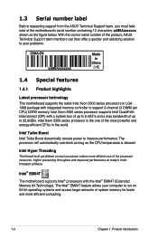
... thread-level parallelism on today's multithreaded software. 1.3 Serial number label Before requesting support from the ASUS Technical Support team, you must take note of the motherboard's serial number containing 12 characters xxM0Axxxxxxx shown as the CPU temperature is the one...your problems. Z8NA-D6 xxM0Axxxxxxx Made in China 合格 1.4 Special features 1.4.1 Product highlights Latest processor technology This motherboard supports the latest Intel Xeon 5500 series processors in the world. With the correct serial number of the product, ASUS Technical Support team members...
... thread-level parallelism on today's multithreaded software. 1.3 Serial number label Before requesting support from the ASUS Technical Support team, you must take note of the motherboard's serial number containing 12 characters xxM0Axxxxxxx shown as the CPU temperature is the one...your problems. Z8NA-D6 xxM0Axxxxxxx Made in China 合格 1.4 Special features 1.4.1 Product highlights Latest processor technology This motherboard supports the latest Intel Xeon 5500 series processors in the world. With the correct serial number of the product, ASUS Technical Support team members...
User Guide
Page 19
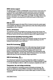
...allows thinner, more flexible cables with USB 1.1. ASUS Z8NA-D6 Series 1-5 The Serial ATA II specification provides twice the bandwidth of the current Serial ATA products with peak bandwidth of up to 32GB/s. USB 2.0 technology The motherboard implements the Universal Serial Bus (USB) 2.0 ...system performance, eliminating bottlenecks with a host of DDR3 which provide a total solution for your networking needs. DDR3 memory support The Z8NA-D6 supports UDIMM and RDIMM DDR3 memory that features data transfer rates of 1333/1066 MHZ to meet the higher bandwidth requirements of...
...allows thinner, more flexible cables with USB 1.1. ASUS Z8NA-D6 Series 1-5 The Serial ATA II specification provides twice the bandwidth of the current Serial ATA products with peak bandwidth of up to 32GB/s. USB 2.0 technology The motherboard implements the Universal Serial Bus (USB) 2.0 ...system performance, eliminating bottlenecks with a host of DDR3 which provide a total solution for your networking needs. DDR3 memory support The Z8NA-D6 supports UDIMM and RDIMM DDR3 memory that features data transfer rates of 1333/1066 MHZ to meet the higher bandwidth requirements of...
User Guide
Page 37
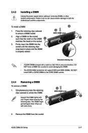
DO NOT force a DIMM into the socket until the retaining clips snap back in only one direction. Remove the DIMM from the socket. ASUS Z8NA-D6 Series 2-17 Align a DIMM on the socket. 3. The DIMM might get damaged when it fits in place and the DIMM is keyed with a notch...DIMM lightly with extra force. 2. Unlocked retaining clip • A DDR3 DIMM is properly seated. Failure to do not support DDR and DDR2 DIMMs. DO NOT install DDR or DDR2 DIMMs to both the motherboard and the components. Firmly insert the DIMM into a socket to avoid damaging the DIMM. • The DDR3 DIMM...
DO NOT force a DIMM into the socket until the retaining clips snap back in only one direction. Remove the DIMM from the socket. ASUS Z8NA-D6 Series 2-17 Align a DIMM on the socket. 3. The DIMM might get damaged when it fits in place and the DIMM is keyed with a notch...DIMM lightly with extra force. 2. Unlocked retaining clip • A DDR3 DIMM is properly seated. Failure to do not support DDR and DDR2 DIMMs. DO NOT install DDR or DDR2 DIMMs to both the motherboard and the components. Firmly insert the DIMM into a socket to avoid damaging the DIMM. • The DDR3 DIMM...
User Guide
Page 38
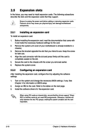
...on the slot. 5. See Chapter 4 for the card. 2. Install the software drivers for later use . Remove the system unit cover (if your motherboard is completely seated on BIOS setup. 2. Align the card connector with the slot and press firmly until the card is already installed in a chassis). 3.... the power cord before adding or removing expansion cards. When using PCI cards on shared slots, ensure that the drivers support "Share IRQ" or that they support. The following subsections describe the slots and the expansion cards that the cards do so may need IRQ assignments. Ensure...
...on the slot. 5. See Chapter 4 for the card. 2. Install the software drivers for later use . Remove the system unit cover (if your motherboard is completely seated on BIOS setup. 2. Align the card connector with the slot and press firmly until the card is already installed in a chassis). 3.... the power cord before adding or removing expansion cards. When using PCI cards on shared slots, ensure that the drivers support "Share IRQ" or that they support. The following subsections describe the slots and the expansion cards that the cards do so may need IRQ assignments. Ensure...

User Guide
Page 40
... cards. 2.5.7 PCI slot The PCI slot supports cards such as a LAN card, USB card, and other cards that comply with PCI 2.3 specifications. 2.5.8 PIKE slot (Z8NA-D6 model only) The PIKE slot allows you to choose and change your needs. Install an optional ASUS PIKE RAID card based on cards like SCSI... RAID card, fiber-channel card, etc. 2.5.6 MIO PCIE slot The MIO PCIE slot only supports a MIO audio card, which offers...
... cards. 2.5.7 PCI slot The PCI slot supports cards such as a LAN card, USB card, and other cards that comply with PCI 2.3 specifications. 2.5.8 PIKE slot (Z8NA-D6 model only) The PIKE slot allows you to choose and change your needs. Install an optional ASUS PIKE RAID card based on cards like SCSI... RAID card, fiber-channel card, etc. 2.5.6 MIO PCIE slot The MIO PCIE slot only supports a MIO audio card, which offers...
User Guide
Page 43
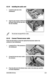
...press firmly until the card sits on your motherboard. 1. This slot does not support PCI-E x1 cards. 2.5.13 Connect Thermal sensor cable Follow the steps below to connect the optional thermal sensor cable to the connector on the slot completely. ASUS Z8NA-D6 Series 2-23 Locate the audio slot... on the motherboard. 2. Place the other end of the ...
...press firmly until the card sits on your motherboard. 1. This slot does not support PCI-E x1 cards. 2.5.13 Connect Thermal sensor cable Follow the steps below to connect the optional thermal sensor cable to the connector on the slot completely. ASUS Z8NA-D6 Series 2-23 Locate the audio slot... on the motherboard. 2. Place the other end of the ...

User Guide
Page 50
... the front panel LED to light up to the SATA or SAS add-on the speed of data transfer rate. RED) (7-pin SATA5, SATA6; Black) Supported by the Intel® ICH10R chipset, these connectors are for the Serial ATA signal cables for the storage add-on card cable connected to 3Gb...
... the front panel LED to light up to the SATA or SAS add-on the speed of data transfer rate. RED) (7-pin SATA5, SATA6; Black) Supported by the Intel® ICH10R chipset, these connectors are for the Serial ATA signal cables for the storage add-on card cable connected to 3Gb...

User Guide
Page 51
SAS connectors (7-pin SAS1, SAS2, SAS3, SAS4; ASUS Z8NA-D6 Series 2-31 Blue) (Z8NA-D6 model only) This motherboard comes with eight (8) Serial Attached SCSI (SAS) connectors, the next-generation storage technology that supports both Serial Attached SCSI (SAS) and Serial ATA (SATA). Each connector supports one device. • These connectors function only when you install a PIKE RAID card. • Connect the SAS hard disk drives to SAS connectors 1-4 (red) when installing a 4-port PIKE RAID card. Red) (7-pin SAS5, SAS6, SAS7, SAS8; 3.
SAS connectors (7-pin SAS1, SAS2, SAS3, SAS4; ASUS Z8NA-D6 Series 2-31 Blue) (Z8NA-D6 model only) This motherboard comes with eight (8) Serial Attached SCSI (SAS) connectors, the next-generation storage technology that supports both Serial Attached SCSI (SAS) and Serial ATA (SATA). Each connector supports one device. • These connectors function only when you install a PIKE RAID card. • Connect the SAS hard disk drives to SAS connectors 1-4 (red) when installing a 4-port PIKE RAID card. Red) (7-pin SAS5, SAS6, SAS7, SAS8; 3.

User Guide
Page 52
A-Type USB5) These connectors are for a serial (COM) port. Connect the serial port module cable to this connector, then install the module to a slot opening at the back of the system chassis. Serial port connector (10-1 pin COM2) This connector is for USB 2.0 ports. Connect the USB module cables to connectors USB34, then install the modules to 480 Mbps connection speed. 5. USB connector (10-1 pin USB34; These USB connectors comply with USB 2.0 specification that supports up to a slot opening at the back of the system chassis. 2-32 Chapter 2: Hardware information 4.
A-Type USB5) These connectors are for a serial (COM) port. Connect the serial port module cable to this connector, then install the module to a slot opening at the back of the system chassis. Serial port connector (10-1 pin COM2) This connector is for USB 2.0 ports. Connect the USB module cables to connectors USB34, then install the modules to 480 Mbps connection speed. 5. USB connector (10-1 pin USB34; These USB connectors comply with USB 2.0 specification that supports up to a slot opening at the back of the system chassis. 2-32 Chapter 2: Hardware information 4.
User Guide
Page 53
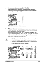
... fan connectors on the fan connectors! • All fans feature the ASUS Smart Fan technology. 6. CPU, front and rear fan connectors (4-pin CPU_FAN1, CPU_FAN2, FRNT_FAN1, FRNT_FAN2, FRNT_FAN3, FRNT_FAN4, REAR_FAN1, REAR_FAN2) The fan connectors support cooling fans of 350 mA-740 mA (8.88 W max.) or a...fan connectors. DO NOT place jumper caps on the motherboard, ensuring that the black wire of each cable matches the ground pin of 3.15 A-6.66 A (53.28 W max.) at +12V. Connect the fan cables to monitor temperature. 7. ASUS Z8NA-D6 Series 2-33 Thermal sensor cable connectors (3-pin...
... fan connectors on the fan connectors! • All fans feature the ASUS Smart Fan technology. 6. CPU, front and rear fan connectors (4-pin CPU_FAN1, CPU_FAN2, FRNT_FAN1, FRNT_FAN2, FRNT_FAN3, FRNT_FAN4, REAR_FAN1, REAR_FAN2) The fan connectors support cooling fans of 350 mA-740 mA (8.88 W max.) or a...fan connectors. DO NOT place jumper caps on the motherboard, ensuring that the black wire of each cable matches the ground pin of 3.15 A-6.66 A (53.28 W max.) at +12V. Connect the fan cables to monitor temperature. 7. ASUS Z8NA-D6 Series 2-33 Thermal sensor cable connectors (3-pin...

User Guide
Page 55
ASUS Z8NA-D6 Series 2-35 Devices communicate with an SMBus host and/or other SMBus devices using the SMBus interface. BMC header (BMC_FW1) (Z8NA-D6 model only) The BMC connector on the motherboard supports an ASUS® Server Management Board 4 Series (ASMB4). 11. Power Supply SMBus connector (5-pin PSUSMB1) This connector allows you to connect SMBus (System Management Bus) to the power supply unit to read PSU information. 10.
ASUS Z8NA-D6 Series 2-35 Devices communicate with an SMBus host and/or other SMBus devices using the SMBus interface. BMC header (BMC_FW1) (Z8NA-D6 model only) The BMC connector on the motherboard supports an ASUS® Server Management Board 4 Series (ASMB4). 11. Power Supply SMBus connector (5-pin PSUSMB1) This connector allows you to connect SMBus (System Management Bus) to the power supply unit to read PSU information. 10.

User Guide
Page 57
...20-pin PANEL1) This connector supports several chassis-mounted functions. 1. Message LED (2-pin MLED) This 2-pin connector is for the chassis-mounted system warning speaker. System warning speaker (4-pin SPEAKER) This 4-pin connector is for the system power LED. ASUS Z8NA-D6 Series 2-37 System power...and warnings. 4. Hard disk drive activity LED (2-pin HDDLED) This 2-pin connector is controlled by Hardware monitor to this connector. ATX power button/soft-off the system power. Connect the chassis power LED cable to indicate an abnormal event occurance. 3. 13. ...
...20-pin PANEL1) This connector supports several chassis-mounted functions. 1. Message LED (2-pin MLED) This 2-pin connector is for the chassis-mounted system warning speaker. System warning speaker (4-pin SPEAKER) This 4-pin connector is for the system power LED. ASUS Z8NA-D6 Series 2-37 System power...and warnings. 4. Hard disk drive activity LED (2-pin HDDLED) This 2-pin connector is controlled by Hardware monitor to this connector. ATX power button/soft-off the system power. Connect the chassis power LED cable to indicate an abnormal event occurance. 3. 13. ...

User Guide
Page 65
...flash disk drive when the BIOS file fails or gets corrupted.) Refer to manage and update the motherboard Basic Input/Output System (BIOS) setup: 1. A:\>afudos /oOLDBIOS1.rom Main filename Extension name ASUS Z8NA-D6 Series 4-3 4.1 Managing and updating your BIOS The following utilities allow you to the corresponding sections... To copy the current BIOS file using a bootable USB flash disk drive.) 2. Copy the AFUDOS utility (afudos.exe) from the motherboard support CD to restore the BIOS in DOS mode using the AFUDOS utility: The succeeding BIOS screens are for the extension name.
...flash disk drive when the BIOS file fails or gets corrupted.) Refer to manage and update the motherboard Basic Input/Output System (BIOS) setup: 1. A:\>afudos /oOLDBIOS1.rom Main filename Extension name ASUS Z8NA-D6 Series 4-3 4.1 Managing and updating your BIOS The following utilities allow you to the corresponding sections... To copy the current BIOS file using a bootable USB flash disk drive.) 2. Copy the AFUDOS utility (afudos.exe) from the motherboard support CD to restore the BIOS in DOS mode using the AFUDOS utility: The succeeding BIOS screens are for the extension name.

User Guide
Page 66
... file on a piece of paper. done Advance Check ...... 3. All rights reserved. Copy the AFUDOS utility (afudos.exe) from the motherboard support CD to prevent system boot failure! 4-4 Chapter 4: BIOS setup A:\>afudos /i8036A0.ROM The utility verifies the file, then starts updating ...65533;e�n��p�r�e�s�s���. A:\>afudos /oOLDBIOS1.rom AMI Firmware Update Utility - Version 1.19(ASUS V2.07(03.11.24BB)) Copyright (C) 2002 American Megatrends, Inc. Press . Updating the BIOS file To update the BIOS file using...
... file on a piece of paper. done Advance Check ...... 3. All rights reserved. Copy the AFUDOS utility (afudos.exe) from the motherboard support CD to prevent system boot failure! 4-4 Chapter 4: BIOS setup A:\>afudos /i8036A0.ROM The utility verifies the file, then starts updating ...65533;e�n��p�r�e�s�s���. A:\>afudos /oOLDBIOS1.rom AMI Firmware Update Utility - Version 1.19(ASUS V2.07(03.11.24BB)) Copyright (C) 2002 American Megatrends, Inc. Press . Updating the BIOS file To update the BIOS file using...


