User Guide
Page 14
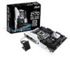
...Clear CMOS jumper 1 x USB BIOS Flashback button 1 x DRCT(Direct Key) connector 1 x TPU switch (advanced two-stage adjustments) 1 x EPU switch 1 x EZ XMP switch 1 x Power-on button 1 x 5-pin EXT_FAN(Extension Fan) connector 128 Mb Flash ROM, UEFI AMI BIOS, PnP, DMI3.0, WfM2.0, SM BIOS 3.0, ACPI 5.0, Multi-language BIOS, ASUS...0Gb/s cables 1 x ASUS SLI bridge connector 1 x ASUS Q-Shield 1 x 2 in 1 Q-connector 1 x Hyper M.2 X4 Mini Card 1 x Hyper Kit 2 x M.2 screw package 1 x user's manual 1 x CPU Installation Tool (continued on the next page) xiv Z170-DELUXE specifications summary Internal I/O ...
...Clear CMOS jumper 1 x USB BIOS Flashback button 1 x DRCT(Direct Key) connector 1 x TPU switch (advanced two-stage adjustments) 1 x EPU switch 1 x EZ XMP switch 1 x Power-on button 1 x 5-pin EXT_FAN(Extension Fan) connector 128 Mb Flash ROM, UEFI AMI BIOS, PnP, DMI3.0, WfM2.0, SM BIOS 3.0, ACPI 5.0, Multi-language BIOS, ASUS...0Gb/s cables 1 x ASUS SLI bridge connector 1 x ASUS Q-Shield 1 x 2 in 1 Q-connector 1 x Hyper M.2 X4 Mini Card 1 x Hyper Kit 2 x M.2 screw package 1 x user's manual 1 x CPU Installation Tool (continued on the next page) xiv Z170-DELUXE specifications summary Internal I/O ...
User Guide
Page 23
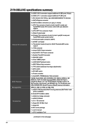
...4-pin CPU_OPT; 5-pin EXT_FAN; 4-pin CHA_FAN1-4) 4. button 6. SATA 6G_34; System panel connector (20-5 pin PANEL) 14. EZ XMP switch 17. Clear CMOS button (CLR_CMOS) 20. Front panel audio connector (10-1 pin AAFP) 25. EPU switch 8. USB1314) 16. Power-on button 18. Q-Code LEDs ... 1-20 1-19 1-31 1-30 1-39 1-22 1-37 1-38 1-34 1-21 1-17 1-17 1-21 2-13 1-38 1-31 1-39 1-32 1-31 1-32 ASUS Z170-DELUXE Series 1-5 TPM connector (20-1 pin TPM) 22. BIOS Flashback button 21. Thunderbolt header (5-pin TB_HEADER) 24. Digital audio connector (4-1 pin SPDIF_OUT) 26. USB ...
...4-pin CPU_OPT; 5-pin EXT_FAN; 4-pin CHA_FAN1-4) 4. button 6. SATA 6G_34; System panel connector (20-5 pin PANEL) 14. EZ XMP switch 17. Clear CMOS button (CLR_CMOS) 20. Front panel audio connector (10-1 pin AAFP) 25. EPU switch 8. USB1314) 16. Power-on button 18. Q-Code LEDs ... 1-20 1-19 1-31 1-30 1-39 1-22 1-37 1-38 1-34 1-21 1-17 1-17 1-21 2-13 1-38 1-31 1-39 1-32 1-31 1-32 ASUS Z170-DELUXE Series 1-5 TPM connector (20-1 pin TPM) 22. BIOS Flashback button 21. Thunderbolt header (5-pin TB_HEADER) 24. Digital audio connector (4-1 pin SPDIF_OUT) 26. USB ...
User Guide
Page 39
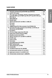
ASUS Z170-DELUXE Series 1-21 Clear CMOS button (CLR_CMOS) Press this switch to overclock the installed DIMMs, allowing you to overclocking. 7. EZ XMP switch Enable this button to clear the BIOS setup information only when the systems hangs due to enhance the DIMM's speed and performance. Chapter 1 6.
ASUS Z170-DELUXE Series 1-21 Clear CMOS button (CLR_CMOS) Press this switch to overclock the installed DIMMs, allowing you to overclocking. 7. EZ XMP switch Enable this button to clear the BIOS setup information only when the systems hangs due to enhance the DIMM's speed and performance. Chapter 1 6.
User Guide
Page 80
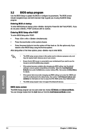
... you want to use the mouse to control the BIOS setup program. • If the system becomes unstable after changing any BIOS setting, try to clear the CMOS and reset the motherboard to the default value. Do this section are for details. • If the system fails to boot after POST: •... on the system chassis. • Press the power button to turn the system off then back on how to erase the RTC RAM via the Clear CMOS button. • The BIOS setup program does not support the Bluetooth devices. Entering BIOS at startup To enter BIOS Setup at startup, press during the...
... you want to use the mouse to control the BIOS setup program. • If the system becomes unstable after changing any BIOS setting, try to clear the CMOS and reset the motherboard to the default value. Do this section are for details. • If the system fails to boot after POST: •... on the system chassis. • Press the power button to turn the system off then back on how to erase the RTC RAM via the Clear CMOS button. • The BIOS setup program does not support the Bluetooth devices. Entering BIOS at startup To enter BIOS Setup at startup, press during the...

User Guide
Page 92
See section 1.2.6 Onboard buttons and switches for information on how to erase the RTC RAM via the Clear CMOS button. • The Administrator or User Password items on top of the screen show [Installed]. 3-14 Chapter 3: BIOS Setup After you to set a password, these ...items show the default [Not Installed]. 3.4 Main menu The Main menu screen appears when you have forgotten your BIOS password, erase the CMOS Real Time Clock (RTC) RAM to clear the BIOS password. Chapter 3 Security The Security menu items allow you to change the system security settings. • If you enter the...
See section 1.2.6 Onboard buttons and switches for information on how to erase the RTC RAM via the Clear CMOS button. • The Administrator or User Password items on top of the screen show [Installed]. 3-14 Chapter 3: BIOS Setup After you to set a password, these ...items show the default [Not Installed]. 3.4 Main menu The Main menu screen appears when you have forgotten your BIOS password, erase the CMOS Real Time Clock (RTC) RAM to clear the BIOS password. Chapter 3 Security The Security menu items allow you to change the system security settings. • If you enter the...


