

User Guide
Page 3
... How this guide is organized x Where to find more information x Z10PE-D16 Series specifications summary xii Chapter 1: Product Introduction 1.1 Welcome!...1-2 1.2 Package contents 1-2 1.3 Serial number label 1-3 1.4 Special features 1-3 1.4.1 Product highlights 1-3 1.4.2 Innovative ASUS features 1-4 Chapter 2: Hardware Information 2.1 Before you proceed 2-2 2.2 Motherboard overview 2-3 2.2.1 Placement direction 2-3 2.2.2 Screw holes 2-3 2.2.3 Motherboard layout 2-4 2.2.4 Layout contents 2-7 2.3 Central Processing Unit (CPU 2-9 2.3.1 Installing the CPU...
... How this guide is organized x Where to find more information x Z10PE-D16 Series specifications summary xii Chapter 1: Product Introduction 1.1 Welcome!...1-2 1.2 Package contents 1-2 1.3 Serial number label 1-3 1.4 Special features 1-3 1.4.1 Product highlights 1-3 1.4.2 Innovative ASUS features 1-4 Chapter 2: Hardware Information 2.1 Before you proceed 2-2 2.2 Motherboard overview 2-3 2.2.1 Placement direction 2-3 2.2.2 Screw holes 2-3 2.2.3 Motherboard layout 2-4 2.2.4 Layout contents 2-7 2.3 Central Processing Unit (CPU 2-9 2.3.1 Installing the CPU...

User Guide
Page 9
...to fix it , carefully read all cables are correctly connected and the power cables are not damaged. Operation safety • Before installing the motherboard and adding devices on a stable surface. • If you add a device. • Before connecting or removing signal cables from the ..., disconnect the power cable from the electrical outlet before relocating the system. • When adding or removing devices to or from the motherboard, ensure that all power cables are unplugged. • Seek professional assistance before using an adapter or extension cord. Contact a qualified service...
...to fix it , carefully read all cables are correctly connected and the power cables are not damaged. Operation safety • Before installing the motherboard and adding devices on a stable surface. • If you add a device. • Before connecting or removing signal cables from the ..., disconnect the power cable from the electrical outlet before relocating the system. • When adding or removing devices to or from the motherboard, ensure that all power cables are unplugged. • Seek professional assistance before using an adapter or extension cord. Contact a qualified service...
User Guide
Page 11
...up sequence and ways of the standard package. Where to find more information Refer to the ASUS contact information. 2. ASUS websites The ASUS website provides updated information on the motherboard. • Chapter 3: Powering up This chapter describes the power up , creating, and configuring...this guide This user guide contains the information you need when installing and configuring the motherboard. It includes description of the switches, jumpers, and connectors on ASUS hardware and software products. Optional documentation Your product package may include optional documentation, such...
...up sequence and ways of the standard package. Where to find more information Refer to the ASUS contact information. 2. ASUS websites The ASUS website provides updated information on the motherboard. • Chapter 3: Powering up This chapter describes the power up , creating, and configuring...this guide This user guide contains the information you need when installing and configuring the motherboard. It includes description of the switches, jumpers, and connectors on ASUS hardware and software products. Optional documentation Your product package may include optional documentation, such...

User Guide
Page 15
Chapter 1: Product Introduction Product introduction This chapter describes the motherboard features and the new technologies it supports. 1
Chapter 1: Product Introduction Product introduction This chapter describes the motherboard features and the new technologies it supports. 1
User Guide
Page 16
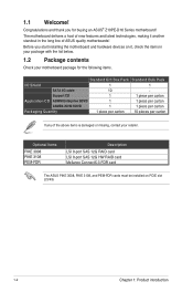
... 1 1 piece per carton Packaging Quantity 1 piece per carton 10 pieces per carton If any of ASUS quality motherboards! Congratulations and thank you start installing the motherboard and hardware devices on PCIE slot 2/3/4/6. 1-2 Chapter 1: Product introduction Optional items PIKE 3008 PIKE 3108 PEM... contents Check your retailer. The motherboard delivers a host of new features and latest technologies, making it , check the items in the long line of the above items is damaged or missing, contact your motherboard package for buying an ASUS® Z10PE-D16 Series motherboard!
... 1 1 piece per carton Packaging Quantity 1 piece per carton 10 pieces per carton If any of ASUS quality motherboards! Congratulations and thank you start installing the motherboard and hardware devices on PCIE slot 2/3/4/6. 1-2 Chapter 1: Product introduction Optional items PIKE 3008 PIKE 3108 PEM... contents Check your retailer. The motherboard delivers a host of new features and latest technologies, making it , check the items in the long line of the above items is damaged or missing, contact your motherboard package for buying an ASUS® Z10PE-D16 Series motherboard!

User Guide
Page 17
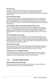
...Voltage Regulator enables generational performance and power improvements that reduces memory power demand and provides improved performance. Z10PE-D16 Series 1-3 Also, Intel's new microarchitecture doubles the cache bandwidth at L1/L2 to support higher FLOPS and contributes to...that the standard VR solutions cannot provide. 1.3 Serial number label Before requesting support from the ASUS Technical Support team, you must take note of the motherboard's serial number containing 12 characters xxS2xxxxxxxx shown in fixed and floating-point algorithm improvements. DDR4 ...
...Voltage Regulator enables generational performance and power improvements that reduces memory power demand and provides improved performance. Z10PE-D16 Series 1-3 Also, Intel's new microarchitecture doubles the cache bandwidth at L1/L2 to support higher FLOPS and contributes to...that the standard VR solutions cannot provide. 1.3 Serial number label Before requesting support from the ASUS Technical Support team, you must take note of the motherboard's serial number containing 12 characters xxS2xxxxxxxx shown in fixed and floating-point algorithm improvements. DDR4 ...
User Guide
Page 18
... partitioning and quality of service of PCIe 2.0. Intel® X540BT2 10GbE LAN controller (Z10PE-D16/10G-2T only) The Intel® 10 Gigabit Ethernet controller X540 is designed with... rotations per minute (RPM) is monitored for critical components. 1.4.2 Innovative ASUS features ASUS Fan Speed control technology The ASUS Fan Speed control technology smartly adjusts the fan speeds according to the system...its complete backward compatibility to 64 virtual ports. Serial ATA III technology The motherboard supports the Serial ATA III technology through the Serial ATA interface and Intel®...
... partitioning and quality of service of PCIe 2.0. Intel® X540BT2 10GbE LAN controller (Z10PE-D16/10G-2T only) The Intel® 10 Gigabit Ethernet controller X540 is designed with... rotations per minute (RPM) is monitored for critical components. 1.4.2 Innovative ASUS features ASUS Fan Speed control technology The ASUS Fan Speed control technology smartly adjusts the fan speeds according to the system...its complete backward compatibility to 64 virtual ports. Serial ATA III technology The motherboard supports the Serial ATA III technology through the Serial ATA interface and Intel®...

User Guide
Page 19
It includes description of the jumpers and connectors on the motherboard. 2 Chapter 2: Hardware Information Hardware Information This chapter lists the hardware setup procedures that you have to perform when installing system components.
It includes description of the jumpers and connectors on the motherboard. 2 Chapter 2: Hardware Information Hardware Information This chapter lists the hardware setup procedures that you have to perform when installing system components.

User Guide
Page 20
..., such as the power supply case, before handling components to avoid damaging them due to static electricity. • Hold components by the edges to the motherboard, peripherals, and/or components. 2-2 Chapter 2: Hardware information 2.1 Before you proceed Take note of the following precautions before you install any...
..., such as the power supply case, before handling components to avoid damaging them due to static electricity. • Hold components by the edges to the motherboard, peripherals, and/or components. 2-2 Chapter 2: Hardware information 2.1 Before you proceed Take note of the following precautions before you install any...

User Guide
Page 21
... chassis. Place this side towards the rear of your chassis to ensure that you place it into the holes indicated by circles to secure the motherboard to unplug the chassis power cord before installing or removing the motherboard. To optimize the features of the chassis Z10PE-D16 Series 2-3
... chassis. Place this side towards the rear of your chassis to ensure that you place it into the holes indicated by circles to secure the motherboard to unplug the chassis power cord before installing or removing the motherboard. To optimize the features of the chassis Z10PE-D16 Series 2-3
User Guide
Page 22
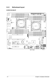
2.2.3 Motherboard layout Z10PE-D16/10G-2T 2-4 Chapter 2: Hardware information
2.2.3 Motherboard layout Z10PE-D16/10G-2T 2-4 Chapter 2: Hardware information

User Guide
Page 27
Triangle mark Z10PE-D16 Series 2-9 Before installing the CPU, ensure that the PnP cap is shipment/ transit-related. • Keep the cap after installing the motherboard. Contact your retailer immediately if the PnP cap is on the top-right position. 2.3 Central Processing Unit (CPU) The motherboard comes with ...the LGA 2011-3 socket. • The product warranty does not cover damage to the PnP cap/socket contacts/motherboard components. ASUS will shoulder the cost of the motherboard, ensure that the socket box is facing toward you and the triangle mark is missing, or if you ...
Triangle mark Z10PE-D16 Series 2-9 Before installing the CPU, ensure that the PnP cap is shipment/ transit-related. • Keep the cap after installing the motherboard. Contact your retailer immediately if the PnP cap is on the top-right position. 2.3 Central Processing Unit (CPU) The motherboard comes with ...the LGA 2011-3 socket. • The product warranty does not cover damage to the PnP cap/socket contacts/motherboard components. ASUS will shoulder the cost of the motherboard, ensure that the socket box is facing toward you and the triangle mark is missing, or if you ...

User Guide
Page 30
... right load lever under the retention tab (M). Push down the left load lever (L) then insert it under the retention tab (K). ASUS will process Return Merchandise Authorization (RMA) requests only if the motherboard comes with the PnP cap on the LGA 2011-3 socket. Retention tab 2-12 Chapter 2: Hardware information 10. Keep the PnP...
... right load lever under the retention tab (M). Push down the left load lever (L) then insert it under the retention tab (K). ASUS will process Return Merchandise Authorization (RMA) requests only if the motherboard comes with the PnP cap on the LGA 2011-3 socket. Retention tab 2-12 Chapter 2: Hardware information 10. Keep the PnP...

User Guide
Page 31
... connect the CPU fan connector! DO NOT forget to the connector on the motherboard labeled CPU_FAN1 / CPU_FAN2. Apply some Thermal Interface Material to plug this step. If it gets into your eyes or touches your skin, wash it . Z10PE-D16 Series 2-13 DO NOT eat it off immediately, and seek professional medical help...
... connect the CPU fan connector! DO NOT forget to the connector on the motherboard labeled CPU_FAN1 / CPU_FAN2. Apply some Thermal Interface Material to plug this step. If it gets into your eyes or touches your skin, wash it . Z10PE-D16 Series 2-13 DO NOT eat it off immediately, and seek professional medical help...

User Guide
Page 32
2.4 System memory 2.4.1 Overview The motherboard comes with the same CAS latency. The figure illustrates the location of the DDR4 DIMM sockets: 2.4.2 Memory Configurations You may install 4 GB, 8 GB, 16 GB, ... GB RDIMMs or 32 GB, 64 GB LR-DIMMs and NVDIMM into the DIMM sockets using the memory configurations in this section. • Refer to ASUS Server AVL for the updated list of compatible DIMMs. • When installing only one DIMM in a single CPU configuration, install the DIMM on either A1...
2.4 System memory 2.4.1 Overview The motherboard comes with the same CAS latency. The figure illustrates the location of the DDR4 DIMM sockets: 2.4.2 Memory Configurations You may install 4 GB, 8 GB, 16 GB, ... GB RDIMMs or 32 GB, 64 GB LR-DIMMs and NVDIMM into the DIMM sockets using the memory configurations in this section. • Refer to ASUS Server AVL for the updated list of compatible DIMMs. • When installing only one DIMM in a single CPU configuration, install the DIMM on either A1...

User Guide
Page 34
... DIMM into the socket VERTICALLY to prevent DIMM notch damage. • To install two or more DIMMs, refer to the user guide bundled with the motherboard package. • Refer to avoid damaging the DIMM. 3. Support the DIMM lightly with your fingers when pressing the retaining clips. Hold the DIMM at both...
... DIMM into the socket VERTICALLY to prevent DIMM notch damage. • To install two or more DIMMs, refer to the user guide bundled with the motherboard package. • Refer to avoid damaging the DIMM. 3. Support the DIMM lightly with your fingers when pressing the retaining clips. Hold the DIMM at both...
User Guide
Page 35
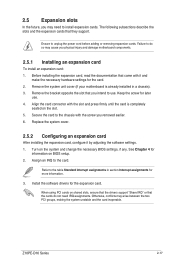
...slot that came with it by adjusting the software settings. 1. Failure to install expansion cards. Remove the system unit cover (if your motherboard is completely seated on shared slots, ensure that the drivers support "Share IRQ" or that they support. See Chapter 4 for the ...you physical injury and damage motherboard components. 2.5.1 Installing an expansion card To install an expansion card: 1. Turn on BIOS setup. 2. When using PCI cards on the slot. 5. Secure the card to the table Standard Interrupt assignments in a chassis). 3. Z10PE-D16 Series 2-17 Refer to the...
...slot that came with it by adjusting the software settings. 1. Failure to install expansion cards. Remove the system unit cover (if your motherboard is completely seated on shared slots, ensure that the drivers support "Share IRQ" or that they support. See Chapter 4 for the ...you physical injury and damage motherboard components. 2.5.1 Installing an expansion card To install an expansion card: 1. Turn on BIOS setup. 2. When using PCI cards on the slot. 5. Secure the card to the table Standard Interrupt assignments in a chassis). 3. Z10PE-D16 Series 2-17 Refer to the...

User Guide
Page 38
... LED lights up to indicate that the ASMB8 is ON, in sleep mode, or in any motherboard component. Baseboard Management Controller LED (BMCLED1) The green heartbeat LED blinks per second to indicate that you enable the ASUS ASMB8. 2-20 Chapter 2: Hardware information The heartbeat LED functions only when you should shut down...
... LED lights up to indicate that the ASMB8 is ON, in sleep mode, or in any motherboard component. Baseboard Management Controller LED (BMCLED1) The green heartbeat LED blinks per second to indicate that you enable the ASUS ASMB8. 2-20 Chapter 2: Hardware information The heartbeat LED functions only when you should shut down...

User Guide
Page 51
... disks installed. • The SSATA4 [Light Gray] will be automatically turned off if the M.2 connector (NGFF) is occupied. Z10PE-D16 Series 2-33 For more information on the SATA RAID solutions supported on this motherboard, refer to the RAID Configuration chapter of this user guide. • The actual data transfer rate depends on the...
... disks installed. • The SSATA4 [Light Gray] will be automatically turned off if the M.2 connector (NGFF) is occupied. Z10PE-D16 Series 2-33 For more information on the SATA RAID solutions supported on this motherboard, refer to the RAID Configuration chapter of this user guide. • The actual data transfer rate depends on the...
User Guide
Page 53
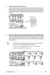
...backward compatibility with USB 2.0. 5. Z10PE-D16 Series 2-35 CPU, front, and rear fan connectors (4-pin CPU_FAN1, CPU_FAN2, FRNT_FAN1, FRNT_FAN2, FRNT_FAN3, FRNT_FAN4, FRNT_FAN5, REAR_FAN1, REAR_FAN2) The fan connectors support cooling fans. Insufficient air flow inside the system may damage the motherboard components. • These are ... module, you to the fan connectors on the fan connectors! • All fans feature the ASUS Smart Fan technology. 4. DO NOT place jumper caps on the motherboard, ensuring that the black wire of each cable matches the ground pin of up to the fan...
...backward compatibility with USB 2.0. 5. Z10PE-D16 Series 2-35 CPU, front, and rear fan connectors (4-pin CPU_FAN1, CPU_FAN2, FRNT_FAN1, FRNT_FAN2, FRNT_FAN3, FRNT_FAN4, FRNT_FAN5, REAR_FAN1, REAR_FAN2) The fan connectors support cooling fans. Insufficient air flow inside the system may damage the motherboard components. • These are ... module, you to the fan connectors on the fan connectors! • All fans feature the ASUS Smart Fan technology. 4. DO NOT place jumper caps on the motherboard, ensuring that the black wire of each cable matches the ground pin of up to the fan...

