User Guide
Page 13
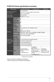
...Z10PE-D16 Series specifications summary Model Name Z10PE-D16/10G-2T Z10PE-D16/4L Z10PE-D16 Processor Support / System Bus 2 x Socket R3 2011 Intel® Xeon® processor E5-2600 V3 product family QPI 6.4 / 8.0 / 9.6 GTps Core Logic Intel® C612 PCH Form Factor SSI EEB, 12 in . Fan Speed Control ASUS... Slots 5 Expansion Slot Location 1 1 x PCI-E x8 (x4 Gen3 link) (MIO supported) Slots (follow Slot Location 2 1 x PCI-E x16 (x16 Gen3 link) SSI Location number) Slot Location 3 1 x PCI-E x8 (x8 Gen3 link) Slot Location 4 1 x PCI-E x16 (x16 Gen3 link) Slot Location 6 1 x PCI...
...Z10PE-D16 Series specifications summary Model Name Z10PE-D16/10G-2T Z10PE-D16/4L Z10PE-D16 Processor Support / System Bus 2 x Socket R3 2011 Intel® Xeon® processor E5-2600 V3 product family QPI 6.4 / 8.0 / 9.6 GTps Core Logic Intel® C612 PCH Form Factor SSI EEB, 12 in . Fan Speed Control ASUS... Slots 5 Expansion Slot Location 1 1 x PCI-E x8 (x4 Gen3 link) (MIO supported) Slots (follow Slot Location 2 1 x PCI-E x16 (x16 Gen3 link) SSI Location number) Slot Location 3 1 x PCI-E x8 (x8 Gen3 link) Slot Location 4 1 x PCI-E x16 (x16 Gen3 link) Slot Location 6 1 x PCI...
User Guide
Page 14
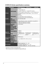
...Z10PE-D16/4L Intel® C612 Z10PE-D16 10 x SATA 6 Gbps ports or 9 x SATA 6 Gbps ports + 1 x discrete M.2 connector Intel® RSTe (supports software RAID 0, 1, 5, and 10, Windows only) LSI® MegaRAID (supports software RAID 0, 1, and 10, Linux and Windows) Optional kits**: ASUS PIKE 3008 8-port SAS 12G RAID card ASUS... PIKE 3108 8-port SAS 12G HW RAID card Aspeed AST2400 32 MB 1 1 x 24-pin SSI power connector + 8-pin SSI 12V + 8-pin SSI 12V 1 x USB 3.0 pin header (up to 2 ...
...Z10PE-D16/4L Intel® C612 Z10PE-D16 10 x SATA 6 Gbps ports or 9 x SATA 6 Gbps ports + 1 x discrete M.2 connector Intel® RSTe (supports software RAID 0, 1, 5, and 10, Windows only) LSI® MegaRAID (supports software RAID 0, 1, and 10, Linux and Windows) Optional kits**: ASUS PIKE 3008 8-port SAS 12G RAID card ASUS... PIKE 3108 8-port SAS 12G HW RAID card Aspeed AST2400 32 MB 1 1 x 24-pin SSI power connector + 8-pin SSI 12V + 8-pin SSI 12V 1 x USB 3.0 pin header (up to 2 ...

User Guide
Page 21
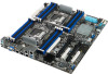
... cause you physical injury and damage motherboard components! 2.2.1 Placement direction When installing the motherboard, ensure that you place it into the chassis in an SSI EEB 2011 1.0 compliant chassis. The edge with external ports goes to the rear part of the chassis as indicated in the image below. 2.2.2 ... can damage the motherboard. Place this side towards the rear of your chassis to the chassis. To optimize the features of the chassis Z10PE-D16 Series 2-3 Failure to unplug the chassis power cord before installing or removing the motherboard. DO NOT overtighten the screws!
... cause you physical injury and damage motherboard components! 2.2.1 Placement direction When installing the motherboard, ensure that you place it into the chassis in an SSI EEB 2011 1.0 compliant chassis. The edge with external ports goes to the rear part of the chassis as indicated in the image below. 2.2.2 ... can damage the motherboard. Place this side towards the rear of your chassis to the chassis. To optimize the features of the chassis Z10PE-D16 Series 2-3 Failure to unplug the chassis power cord before installing or removing the motherboard. DO NOT overtighten the screws!