

P3C-E User Manual
Page 5
... 6.3 Using YAMAHA XGstudio Mixer 105 7. APPENDIX 107 7.1 PCI-L101 Fast Ethernet Card 107 7.2 Modem Riser (optional 109 ASUS P3C-E User's Manual 5 CONTENTS 4. SOFTWARE SETUP 81 5.1 Operating Systems 81 5.2 P3C Series Motherboard Support CD 82 5.3 Intel LDCM Administrator Setup 84 5.4 Intel LDCM Client Setup 86 5.5 INF Update Utility for Intel 820 Chipset 88 5.6 Install YAMAHA XG Audio Driver (VxD only with onboard audio option 89 5.7 Install YAMAHA XG Studio Audio Application (only with onboard audio option 90 5.8 Install YAMAHA...
... 6.3 Using YAMAHA XGstudio Mixer 105 7. APPENDIX 107 7.1 PCI-L101 Fast Ethernet Card 107 7.2 Modem Riser (optional 109 ASUS P3C-E User's Manual 5 CONTENTS 4. SOFTWARE SETUP 81 5.1 Operating Systems 81 5.2 P3C Series Motherboard Support CD 82 5.3 Intel LDCM Administrator Setup 84 5.4 Intel LDCM Client Setup 86 5.5 INF Update Utility for Intel 820 Chipset 88 5.6 Install YAMAHA XG Audio Driver (VxD only with onboard audio option 89 5.7 Install YAMAHA XG Studio Audio Application (only with onboard audio option 90 5.8 Install YAMAHA...

P3C-E User Manual
Page 7
... Ribbon cable for master and slave UltraDMA/66 or UltraDMA/33 IDE drives (1) Ribbon cable for (1) 5.25" and (2) 3.5" floppy disk drives (1) Bag of spare jumpers (1) Support drivers and utilities (1) This Motherboard User's Manual ASUS DR2 DIMM riser (optional) ASUS S370 Series CPU card (optional) ASUS IrDA-compliant infrared module (optional) ASUS PCI-L101 Wake-On-LAN 10/100 ethernet card (optional) ASUS P3C-E User's Manual 7 BIOS SETUP 5. APPENDIX Manual information and checklist Production information and specifications Intructions on setting up the motherboard. HARDWARE SETUP...
... Ribbon cable for master and slave UltraDMA/66 or UltraDMA/33 IDE drives (1) Ribbon cable for (1) 5.25" and (2) 3.5" floppy disk drives (1) Bag of spare jumpers (1) Support drivers and utilities (1) This Motherboard User's Manual ASUS DR2 DIMM riser (optional) ASUS S370 Series CPU card (optional) ASUS IrDA-compliant infrared module (optional) ASUS PCI-L101 Wake-On-LAN 10/100 ethernet card (optional) ASUS P3C-E User's Manual 7 BIOS SETUP 5. APPENDIX Manual information and checklist Production information and specifications Intructions on setting up the motherboard. HARDWARE SETUP...

P3C-E User Manual
Page 8
... IDE DMA Mode 2, and Enhanced IDE devices, such as an option). • AGP Pro Slot: Supports the new Accelerated Graphics Port Pro card for AGP 4X mode, which will improve cryptography, digital signing, and other security protocols. • PC800 Memory Support: Equipped with two connectors that support four IDE devices on two channels. Easy-to-use DIP switches instead of the processor's external frequency. 8 ASUS P3C-E User's Manual FEA TURES Specifications 2. These sockets...
... IDE DMA Mode 2, and Enhanced IDE devices, such as an option). • AGP Pro Slot: Supports the new Accelerated Graphics Port Pro card for AGP 4X mode, which will improve cryptography, digital signing, and other security protocols. • PC800 Memory Support: Equipped with two connectors that support four IDE devices on two channels. Easy-to-use DIP switches instead of the processor's external frequency. 8 ASUS P3C-E User's Manual FEA TURES Specifications 2. These sockets...

P3C-E User Manual
Page 9
... slot (optional) to support legacy add-on cards. (PCI supports up to examine and manage system status information, such as CPU and systerm voltages, temperatures, and fan status through a new design, battery drain is used for wireless interfacing with EPP and ECP capabilities. Hardware random number generator supports new security software for data protection and secured Internet transactions. • IrDA: Supports an optional infrared port module for virtually automatic setup. • Smart BIOS: 4Mb firmware gives a new...
... slot (optional) to support legacy add-on cards. (PCI supports up to examine and manage system status information, such as CPU and systerm voltages, temperatures, and fan status through a new design, battery drain is used for wireless interfacing with EPP and ECP capabilities. Hardware random number generator supports new security software for data protection and secured Internet transactions. • IrDA: Supports an optional infrared port module for virtually automatic setup. • Smart BIOS: 4Mb firmware gives a new...
P3C-E User Manual
Page 11
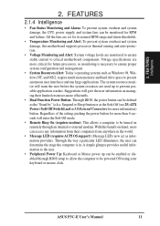
...'s operating systems such as the "Stand by" (a.k.a. 2. A simple glimpse provides useful information to the user. • Peripheral Power Up: Keyboard or Mouse power up to critical motherboard components. Through the way a particular LED illuminates, the user can be enabled or disabled through an internal or external modem. Voltage specifications are more memory and hard drive space to present enormous user interfaces and run large applications. The system resource monitor will enter the...
...'s operating systems such as the "Stand by" (a.k.a. 2. A simple glimpse provides useful information to the user. • Peripheral Power Up: Keyboard or Mouse power up to critical motherboard components. Through the way a particular LED illuminates, the user can be enabled or disabled through an internal or external modem. Voltage specifications are more memory and hard drive space to present enormous user interfaces and run large applications. The system resource monitor will enter the...
P3C-E User Manual
Page 12
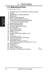
FEATURES 2.2 Motherboard Parts See opposite page for locations. 1 ATX Power Connector for connection to an ATX power supply 2 CPU Slot 1 3 Intel 820 Memory Controller Hub (MCH) 4 RIMM Sockets 5 Intel I/O Controller Hub (ICH) 6 Primary and Secondary IDE Connectors 7 Four Mbit Firmware Hub (Programmable BIOS) 8 Low Pin Count (LPC) Multi-I/O Chipset 9 Floppy Disk Drive Connector 10 Feature Setting DIP Switches 11 ASUS ASIC with Hardware Monitor 12 PCI-to-ISA Bridge 13 Wake-On-Ring Connector 14 Wake-On-LAN Connector 15 ISA Slot (optional) 16...
FEATURES 2.2 Motherboard Parts See opposite page for locations. 1 ATX Power Connector for connection to an ATX power supply 2 CPU Slot 1 3 Intel 820 Memory Controller Hub (MCH) 4 RIMM Sockets 5 Intel I/O Controller Hub (ICH) 6 Primary and Secondary IDE Connectors 7 Four Mbit Firmware Hub (Programmable BIOS) 8 Low Pin Count (LPC) Multi-I/O Chipset 9 Floppy Disk Drive Connector 10 Feature Setting DIP Switches 11 ASUS ASIC with Hardware Monitor 12 PCI-to-ISA Bridge 13 Wake-On-Ring Connector 14 Wake-On-LAN Connector 15 ISA Slot (optional) 16...
P3C-E User Manual
Page 15
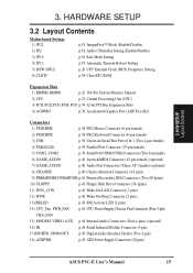
...; Mode (Enable/Disable) p.18 Audio COntroller Setting (Enable/Disable) p.19 Safe Mode Setting p.19 Automatic Timeout Reboot Setting p.20 CPU External Clock (BUS) Frequency Setting p.59 Clear RTC RAM Expansion Slots 1) RIMM0, RIMM1 p.22 184-Pin System Memory Support 2) CPU p.27 Central Processing Unit (CPU) 3) PCI1, PCI2, PCI3, PCI4, PCI5 p.34 32-bit PCI Bus Expansion Slots 4) AGPPRO p.36 Accelerated Graphics Port (AGP Pro) Slot Connectors 1) PS2KBMS p.38 PS/2 Mouse Connector (6-pin female) 2) PS2KBMS p.38 PS/2 Keyboard Connector (6-pin female) 3) USB p.39 Universal Serial Bus...
...; Mode (Enable/Disable) p.18 Audio COntroller Setting (Enable/Disable) p.19 Safe Mode Setting p.19 Automatic Timeout Reboot Setting p.20 CPU External Clock (BUS) Frequency Setting p.59 Clear RTC RAM Expansion Slots 1) RIMM0, RIMM1 p.22 184-Pin System Memory Support 2) CPU p.27 Central Processing Unit (CPU) 3) PCI1, PCI2, PCI3, PCI4, PCI5 p.34 32-bit PCI Bus Expansion Slots 4) AGPPRO p.36 Accelerated Graphics Port (AGP Pro) Slot Connectors 1) PS2KBMS p.38 PS/2 Mouse Connector (6-pin female) 2) PS2KBMS p.38 PS/2 Keyboard Connector (6-pin female) 3) USB p.39 Universal Serial Bus...
P3C-E User Manual
Page 17
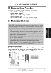
... when working on the motherboard. To protect them against damage from the system. 5. Use a grounded wrist strap before you must complete the following steps: • Check Motherboard Settings • Install Memory Modules • Install the Central Processing Unit (CPU) • Install Expansion Cards • Connect Ribbon Cables, Panel Wires, and Power Supply 3.4 Motherboard Settings WARNING! Frequency Selection 3. The example below shows all the switches in or remove the ATX power connector on the inside. 2.
... when working on the motherboard. To protect them against damage from the system. 5. Use a grounded wrist strap before you must complete the following steps: • Check Motherboard Settings • Install Memory Modules • Install the Central Processing Unit (CPU) • Install Expansion Cards • Connect Ribbon Cables, Panel Wires, and Power Supply 3.4 Motherboard Settings WARNING! Frequency Selection 3. The example below shows all the switches in or remove the ATX power connector on the inside. 2.

P3C-E User Manual
Page 18
... the BIOS setup (see 3.7.3 Audio Modem Riser (AMR) Slot). If using a PCI audio card on any of the expansion slots or a primary AMR on model with onboard audio) This jumper allows you to enable or disable the onboard 32-bit PCI audio controller (optional component). H/W SETUP Motherboard Settings 3. Setting Enable Disable JP2 [1-2] (default) [2-3] P3C-E JP2 1 2 3 Enable 1 2 3 Disable P3C-E Audio Controller Setting 18 ASUS P3C-E User's Manual ON 12345 3. The JumperFree™ mode allows processor settings to be set to OFF. HARDWARE SETUP 1) JumperFree™ Mode (JP22...
... the BIOS setup (see 3.7.3 Audio Modem Riser (AMR) Slot). If using a PCI audio card on any of the expansion slots or a primary AMR on model with onboard audio) This jumper allows you to enable or disable the onboard 32-bit PCI audio controller (optional component). H/W SETUP Motherboard Settings 3. Setting Enable Disable JP2 [1-2] (default) [2-3] P3C-E JP2 1 2 3 Enable 1 2 3 Disable P3C-E Audio Controller Setting 18 ASUS P3C-E User's Manual ON 12345 3. The JumperFree™ mode allows processor settings to be set to OFF. HARDWARE SETUP 1) JumperFree™ Mode (JP22...

P3C-E User Manual
Page 19
... problem. If rebooting is possible through motherboard settings or BIOS setup. With unlocked socket 370 processors, exceeding the specified multiple is repeating ineffectively, set so that when the BIOS detects a hang (timeout) during bootup. 3. H/W SETUP Motherboard Settings JP12 1 23 123 P3C-E Normal No Reboot (Default) P3C-E Automatic Timeout Reboot Setting ASUS P3C-E User's Manual 19 In this occurs, enable Safe Mode to force a multiple of 2 and 100MHz FSB to enter BIOS setup to Safe Mode...
... problem. If rebooting is possible through motherboard settings or BIOS setup. With unlocked socket 370 processors, exceeding the specified multiple is repeating ineffectively, set so that when the BIOS detects a hang (timeout) during bootup. 3. H/W SETUP Motherboard Settings JP12 1 23 123 P3C-E Normal No Reboot (Default) P3C-E Automatic Timeout Reboot Setting ASUS P3C-E User's Manual 19 In this occurs, enable Safe Mode to force a multiple of 2 and 100MHz FSB to enter BIOS setup to Safe Mode...

P3C-E User Manual
Page 34
... the slot you removed above. 5. Secure the card on shared slots, make the system unstable or cards inoperable. Replace the computer system's cover. 6. Set up the BIOS if necessary (such as jumpers. 2. Generally, an IRQ must be exclusively assigned to both your motherboard also has MIDI enabled, another IRQ will be used . If your motherboard and expansion cards. 3.7.1 Expansion Card Installation Procedure 1. INT-B - shared - shared - 34 ASUS P3C-E User's Manual HARDWARE SETUP 3.7 Expansion Cards...
... the slot you removed above. 5. Secure the card on shared slots, make the system unstable or cards inoperable. Replace the computer system's cover. 6. Set up the BIOS if necessary (such as jumpers. 2. Generally, an IRQ must be exclusively assigned to both your motherboard also has MIDI enabled, another IRQ will be used . If your motherboard and expansion cards. 3.7.1 Expansion Card Installation Procedure 1. INT-B - shared - shared - 34 ASUS P3C-E User's Manual HARDWARE SETUP 3.7 Expansion Cards...
P3C-E User Manual
Page 36
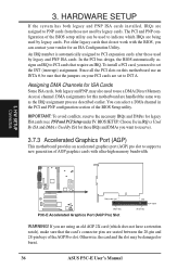
... also need to use an INTA #, be sure that do not work with ultra-high memory bandwidth. 3. If you want to reserve). 3.7.3 Accelerated Graphics Port (AGP) This motherboard provides an accelerated graphics port (AGP) pro slot to PNP cards from those used to PCI cards that the card's connector pins are seated between the 20-pin and 28-pin bays of the BIOS Setup utility. H/W SETUP Connectors PARALLEL PORT OPTIONAL 1 2 3 4 P3C-E Rib (inside slot) 20-pin bay P3C-E Accelerated Graphics Port...
... also need to use an INTA #, be sure that do not work with ultra-high memory bandwidth. 3. If you want to reserve). 3.7.3 Accelerated Graphics Port (AGP) This motherboard provides an accelerated graphics port (AGP) pro slot to PNP cards from those used to PCI cards that the card's connector pins are seated between the 20-pin and 28-pin bays of the BIOS Setup utility. H/W SETUP Connectors PARALLEL PORT OPTIONAL 1 2 3 4 P3C-E Rib (inside slot) 20-pin bay P3C-E Accelerated Graphics Port...

P3C-E User Manual
Page 47
... power switch after Windows shuts down to your system case according to enter BIOS setup. H/W SETUP Power Connections 3. After all switches are made, close the system case cover. 2. Your monitor b. For ATX power supplies, you use Windows 95, click the Start button, click Shut Down, and then click Shut down your operating system before switching OFF the power switch. Recheck your jumper settings and connections or call your devices in 4. ASUS P3C-E User's Manual 47 Be sure that is pressed. External SCSI devices (starting...
... power switch after Windows shuts down to your system case according to enter BIOS setup. H/W SETUP Power Connections 3. After all switches are made, close the system case cover. 2. Your monitor b. For ATX power supplies, you use Windows 95, click the Start button, click Shut Down, and then click Shut down your operating system before switching OFF the power switch. Recheck your jumper settings and connections or call your devices in 4. ASUS P3C-E User's Manual 47 Be sure that is pressed. External SCSI devices (starting...
P3C-E User Manual
Page 57
... drive information you entered. This field can also be set to suppress Ultra DMA capability. Configuration options: [0] [1] [2] [3] [4] [Disabled] 4. NOTE: To make changes to [User Type HDD]. Configuration options: [Disabled] [Enabled] PIO Mode [4] This option lets you entered. BIOS SETUP Master/Slave Drives ASUS P3C-E User's Manual 57 Refer to your drive documentation to determine the correct value to [User Type HDD] and the Translation Method field must be set to the highest number supported by the BIOS from the drive information you set to enter...
... drive information you entered. This field can also be set to suppress Ultra DMA capability. Configuration options: [0] [1] [2] [3] [4] [Disabled] 4. NOTE: To make changes to [User Type HDD]. Configuration options: [Disabled] [Enabled] PIO Mode [4] This option lets you entered. BIOS SETUP Master/Slave Drives ASUS P3C-E User's Manual 57 Refer to your drive documentation to determine the correct value to [User Type HDD] and the Translation Method field must be set to the highest number supported by the BIOS from the drive information you set to enter...
P3C-E User Manual
Page 66
... IR connector. BIOS SETUP UART2 Use Standard Infrared [Disabled] When enabled, this feature, Parallel Port Mode and ECP DMA Select configurations will no longer work if you to set the operation mode of the onboard parallel port connector. Configuration options: [1] [3] [Disabled] Onboard CIR I /O Device Config 66 ASUS P3C-E User's Manual See IrDA-Compliant Infrared Module Connector in a two-way mode. Configuration options: [Disabled] [Enabled] Onboard Parallel Port [378H/IRQ7] This field sets the address of the parallel port. [Normal] allows normal-speed operation...
... IR connector. BIOS SETUP UART2 Use Standard Infrared [Disabled] When enabled, this feature, Parallel Port Mode and ECP DMA Select configurations will no longer work if you to set the operation mode of the onboard parallel port connector. Configuration options: [1] [3] [Disabled] Onboard CIR I /O Device Config 66 ASUS P3C-E User's Manual See IrDA-Compliant Infrared Module Connector in a two-way mode. Configuration options: [Disabled] [Enabled] Onboard Parallel Port [378H/IRQ7] This field sets the address of the parallel port. [Normal] allows normal-speed operation...

P3C-E User Manual
Page 68
... the displayed IRQ is not used or that ISA Configuration Utility (ICU) is being used to determine if an ISA card is using an ICU, you install a legacy ISA card that requires IRQ 10, then set IRQ10 Used By ISA to [Yes]. BIOS SETUP PCI Configuration 68 ASUS P3C-E User's Manual If you install a legacy ISA card that requires a unique IRQ and you are not using that IRQ to [Yes]. BIOS SETUP PCI/PNP...
... the displayed IRQ is not used or that ISA Configuration Utility (ICU) is being used to determine if an ISA card is using an ICU, you install a legacy ISA card that requires IRQ 10, then set IRQ10 Used By ISA to [Yes]. BIOS SETUP PCI Configuration 68 ASUS P3C-E User's Manual If you install a legacy ISA card that requires a unique IRQ and you are not using that IRQ to [Yes]. BIOS SETUP PCI/PNP...
P3C-E User Manual
Page 73
The DPMS (Display Power Management System) feature allows the BIOS to control the video display card if it supports the DPMS feature. [Blank Screen] only blanks the screen (use on the motherboard do not support the STR function, you use this user-configurable field. This feature does not affect SCSI hard drives. If the power supply meets the requirement, the STR function will be disabled. if not, this field on the +5VSB lead...
The DPMS (Display Power Management System) feature allows the BIOS to control the video display card if it supports the DPMS feature. [Blank Screen] only blanks the screen (use on the motherboard do not support the STR function, you use this user-configurable field. This feature does not affect SCSI hard drives. If the power supply meets the requirement, the STR function will be disabled. if not, this field on the +5VSB lead...

P3C-E User Manual
Page 82
5. S/W SETUP Windows 98 • Intel LDCM Administrator Setup: Installs software to change at any time without notice. To begin using your support CD disc, just insert it into your computer's fan, temperature, and voltages. • Install ASUS Update V2.24: Installs a program to run D:\ASSETUP.EXE (assuming that your BIOS or download a BIOS image file. 82 P3C-E User's Manual The administrator should appear. SOFTWARE SETUP 5.2 P3C Series Motherboard Support CD NOTE: The support CD contents are subject to...
5. S/W SETUP Windows 98 • Intel LDCM Administrator Setup: Installs software to change at any time without notice. To begin using your support CD disc, just insert it into your computer's fan, temperature, and voltages. • Install ASUS Update V2.24: Installs a program to run D:\ASSETUP.EXE (assuming that your BIOS or download a BIOS image file. 82 P3C-E User's Manual The administrator should appear. SOFTWARE SETUP 5.2 P3C Series Motherboard Support CD NOTE: The support CD contents are subject to...

P3C-E User Manual
Page 104
... correctly set Select the YAMAHA SGMP Driver Select the YAMAHA SXG50 Driver Select the YAMAHA CBX Driver Refer to increase the free space on your tone generator. 104 ASUS P3C-E User's Manual SOFTWARE REFERENCE 6.2.2 Troubleshooting Cannot install • Do you have the required hardware, such as hard disk and memory? • Do you have connected an external tone generator via a serial cable, is heard correctly? 6.2.3 About the driver To use will...
... correctly set Select the YAMAHA SGMP Driver Select the YAMAHA SXG50 Driver Select the YAMAHA CBX Driver Refer to increase the free space on your tone generator. 104 ASUS P3C-E User's Manual SOFTWARE REFERENCE 6.2.2 Troubleshooting Cannot install • Do you have the required hardware, such as hard disk and memory? • Do you have connected an external tone generator via a serial cable, is heard correctly? 6.2.3 About the driver To use will...

P3C-E User Manual
Page 110
... communication software. Power ON the computer after the hardware installation is located, click Next and then click Finish. 6. APPENDIX Modem Riser 7. Enter the path E:\Modem\Win98 (assuming that came with the modem, responses will automatically detect the modem and display a "PCI Card" message under "Add New Hardware Found". 3. Click Diagnostic and then click the designated COM port as shown. 110 ASUS P3C-E User's Manual Click Start, point to install...
... communication software. Power ON the computer after the hardware installation is located, click Next and then click Finish. 6. APPENDIX Modem Riser 7. Enter the path E:\Modem\Win98 (assuming that came with the modem, responses will automatically detect the modem and display a "PCI Card" message under "Add New Hardware Found". 3. Click Diagnostic and then click the designated COM port as shown. 110 ASUS P3C-E User's Manual Click Start, point to install...


