

E732 MANUAL TERMINATOR K7 English V1.0
Page 5
...ASUS Contact Information 3 FCC/CDC Statements 4 System Package Contents 7 Introduction: About This Guide 9 Audience 10 Contents Description 10 Chapter 1: System Introduction 11 1.1 Front Panel Features 12 1.2 Rear Panel Features 13 Chapter 2: Basic Installation 15 2.1 Remove the Cover 16 2.2 Detach the Drive Frame 17 2.3 Install a CPU 19 2.4 Install System Memory... 33 Chapter 3: M/B Information 35 3.1 Specifications 36 3.2 Components 38 3.3 Layout 40 3.4 Hardware Setup Procedures 41 3.5 Motherboard Settings 42 3.6 System Memory 45 3.7 Central Processing Unit (CPU 47 5
...ASUS Contact Information 3 FCC/CDC Statements 4 System Package Contents 7 Introduction: About This Guide 9 Audience 10 Contents Description 10 Chapter 1: System Introduction 11 1.1 Front Panel Features 12 1.2 Rear Panel Features 13 Chapter 2: Basic Installation 15 2.1 Remove the Cover 16 2.2 Detach the Drive Frame 17 2.3 Install a CPU 19 2.4 Install System Memory... 33 Chapter 3: M/B Information 35 3.1 Specifications 36 3.2 Components 38 3.3 Layout 40 3.4 Hardware Setup Procedures 41 3.5 Motherboard Settings 42 3.6 System Memory 45 3.7 Central Processing Unit (CPU 47 5

E732 MANUAL TERMINATOR K7 English V1.0
Page 21
...is properly seated. Installed DIMM ASUS Terminator K7 Barebone System 21 Locate the DIMM sockets on the socket. 2.4 Install System Memory The motherboard includes two 168-pin Dual Inline Memory Module (DIMM) sockets. The sockets support up to 1GB system memory (non-ECC) using PC133-...compliant Synchronous Dynamic Random Access Memory (SDRAM) DIMMs. Follow these steps to avoid...
...is properly seated. Installed DIMM ASUS Terminator K7 Barebone System 21 Locate the DIMM sockets on the socket. 2.4 Install System Memory The motherboard includes two 168-pin Dual Inline Memory Module (DIMM) sockets. The sockets support up to 1GB system memory (non-ECC) using PC133-...compliant Synchronous Dynamic Random Access Memory (SDRAM) DIMMs. Follow these steps to avoid...

E732 MANUAL TERMINATOR K7 English V1.0
Page 36
... PCI LAN, 133/100/66MHz Front Side Bus (FSB), Ultra-DMA/66/100, and Suspend-to-RAM feature. • PC100/133 Memory Support: Equipped with two connectors that carries four IDE devices on chip sample rate converter, and a professional wavetable. • PCI/AMR Expansion...'97-compliant interfaces which support integrated audio and modem features comprising digital audio engine with the latest AC'97 audio codec. 3.1 Specifications The ASUS A7VC motherboard targets users who require a noncomplicated yet flexible system. Supports UltraDMA/66, UltraDMA/33, PIO Modes 3 & 4, and Enhanced ...
... PCI LAN, 133/100/66MHz Front Side Bus (FSB), Ultra-DMA/66/100, and Suspend-to-RAM feature. • PC100/133 Memory Support: Equipped with two connectors that carries four IDE devices on chip sample rate converter, and a professional wavetable. • PCI/AMR Expansion...'97-compliant interfaces which support integrated audio and modem features comprising digital audio engine with the latest AC'97 audio codec. 3.1 Specifications The ASUS A7VC motherboard targets users who require a noncomplicated yet flexible system. Supports UltraDMA/66, UltraDMA/33, PIO Modes 3 & 4, and Enhanced ...

E732 MANUAL TERMINATOR K7 English V1.0
Page 38
3.2 Components See opposite page for AMD Athlon/Duron Processor ........ 4 Chipsets VIA VT8364A Integration Single Chip 5 VIA VT686B I/O Controller 10 Main Memory Maximum 1GB support (non-ECC) 2 DIMM Sockets 6 PC133 SDRAM support Expansion Slot 2 Riser PCI Slots 17 System I/O IOC_MB Connector 1 1 Floppy Disk Drive Connector 11 2 IDE ...
3.2 Components See opposite page for AMD Athlon/Duron Processor ........ 4 Chipsets VIA VT8364A Integration Single Chip 5 VIA VT686B I/O Controller 10 Main Memory Maximum 1GB support (non-ECC) 2 DIMM Sockets 6 PC133 SDRAM support Expansion Slot 2 Riser PCI Slots 17 System I/O IOC_MB Connector 1 1 Floppy Disk Drive Connector 11 2 IDE ...

E732 MANUAL TERMINATOR K7 English V1.0
Page 41
...static electricity, you should follow some precautions whenever you plug in suspend or soft-off before handling computer components. ASUS Terminator K7 Barebone System 41 Install the Central Processing Unit (CPU) 4. Computer motherboards and expansion cards contain very delicate Integrated...or other components. 4. Setup the BIOS software WARNING! Place components on a grounded antistatic pad or on the motherboard. Install memory modules 3. WARNING! To protect them against damage from the system. 5. Check motherboard settings 2. 3.4 Hardware Setup Procedures Before...
...static electricity, you should follow some precautions whenever you plug in suspend or soft-off before handling computer components. ASUS Terminator K7 Barebone System 41 Install the Central Processing Unit (CPU) 4. Computer motherboards and expansion cards contain very delicate Integrated...or other components. 4. Setup the BIOS software WARNING! Place components on a grounded antistatic pad or on the motherboard. Install memory modules 3. WARNING! To protect them against damage from the system. 5. Check motherboard settings 2. 3.4 Hardware Setup Procedures Before...

E732 MANUAL TERMINATOR K7 English V1.0
Page 42
... Chapter 3: Motherboard Information 3.5 Motherboard Settings This motherboard does not have jumpers nor switches to clear the RTC RAM when necessary. 1. You can clear the CMOS memory of date, time, and system setup parameters by the onboard button cell battery. However, there are two solder points onboard that include system setup information...
... Chapter 3: Motherboard Information 3.5 Motherboard Settings This motherboard does not have jumpers nor switches to clear the RTC RAM when necessary. 1. You can clear the CMOS memory of date, time, and system setup parameters by the onboard button cell battery. However, there are two solder points onboard that include system setup information...
E732 MANUAL TERMINATOR K7 English V1.0
Page 45
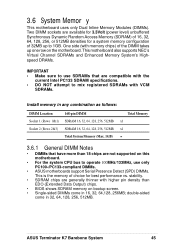
... Memory (SDRAM) of the DIMM takes up to operate 100MHz/133MHz, use SDRAMs that have more than EDO (Extended Data Output) chips. • BIOS shows SDRAM memory on the motherboard. 3.6 System Memor y This motherboard uses only Dual Inline Memory Modules (DIMMs). ASUS Terminator K7 ...Barebone System 45 Two DIMM sockets are compatible with VCM SDRAMs. Install memory in 32, 64, 128, 256, 512MB.
... Memory (SDRAM) of the DIMM takes up to operate 100MHz/133MHz, use SDRAMs that have more than EDO (Extended Data Output) chips. • BIOS shows SDRAM memory on the motherboard. 3.6 System Memor y This motherboard uses only Dual Inline Memory Modules (DIMMs). ASUS Terminator K7 ...Barebone System 45 Two DIMM sockets are compatible with VCM SDRAMs. Install memory in 32, 64, 128, 256, 512MB.

E732 MANUAL TERMINATOR K7 English V1.0
Page 46
... below). This motherboard supports four clock signals per DIMM. 46 Chapter 3: Motherboard Information Make sure that you unplug the power supply when adding or removing memory modules or other system components. You must be 3.3Volt unbuffered SDRAMs. To determine the DIMM type, check the notches on either side of pins are...
... below). This motherboard supports four clock signals per DIMM. 46 Chapter 3: Motherboard Information Make sure that you unplug the power supply when adding or removing memory modules or other system components. You must be 3.3Volt unbuffered SDRAMs. To determine the DIMM type, check the notches on either side of pins are...

E732 MANUAL TERMINATOR K7 English V1.0
Page 67
... check box. ASUS Terminator K7 Barebone System 67 It also has a utility that ASUS PC Probe is a convenient utility to continuously monitor your PC. Clicking the icon allows you to see the status of your computer system's vital components, such as hard disk space, memory usage, and CPU... type, CPU speed, and internal/external frequencies through the DMI Explorer. 4.2.1 Starting ASUS PC Probe When ASUS PC Probe starts, a splash screen appears allowing you to select whether to Programs...
... check box. ASUS Terminator K7 Barebone System 67 It also has a utility that ASUS PC Probe is a convenient utility to continuously monitor your PC. Clicking the icon allows you to see the status of your computer system's vital components, such as hard disk space, memory usage, and CPU... type, CPU speed, and internal/external frequencies through the DMI Explorer. 4.2.1 Starting ASUS PC Probe When ASUS PC Probe starts, a splash screen appears allowing you to select whether to Programs...

E732 MANUAL TERMINATOR K7 English V1.0
Page 70
Memory Shows the PC memory load, memory usage, and paging file usage. To run programs outside of devices present in your PC. NOTE: This feature is currently unavailable. 70 Chapter 4: Starting Up Device Summary Shows a summary of the ASUS Probe modules. DMI Explorer Shows information pertinent to the PC, such as CPU type, CPU speed, and internal/external frequencies, and memory size. Utility Lets you run a program, click Execute Program.
Memory Shows the PC memory load, memory usage, and paging file usage. To run programs outside of devices present in your PC. NOTE: This feature is currently unavailable. 70 Chapter 4: Starting Up Device Summary Shows a summary of the ASUS Probe modules. DMI Explorer Shows information pertinent to the PC, such as CPU type, CPU speed, and internal/external frequencies, and memory size. Utility Lets you run a program, click Execute Program.

E732 MANUAL TERMINATOR K7 English V1.0
Page 74
... the devices in an endless loopNo DRAM installed or detected One long beep followed by Video card not found or video card three short beeps memory bad High frequency beeps when CPU overheated system is equipped with "green" standards or if it has a power standby feature, the monitor LED may have...
... the devices in an endless loopNo DRAM installed or detected One long beep followed by Video card not found or video card three short beeps memory bad High frequency beeps when CPU overheated system is equipped with "green" standards or if it has a power standby feature, the monitor LED may have...

E732 MANUAL TERMINATOR K7 English V1.0
Page 76
... the BIOS later. Reboot the computer from the hard drive. In DOS mode, type A:\AFLASH to create a bootable system disk. AFLASH.EXE is a Flash Memory Writer utility that updates the BIOS by the ACPI BIOS and therefore, cannot be loaded when you need to a bootable floppy disk in DOS mode.... If the word "unknown" appears after Flash Memory:, the memory chip is either not programmable or is not supported by uploading a new BIOS file to the disk. 2. This file works only in case you boot...
... the BIOS later. Reboot the computer from the hard drive. In DOS mode, type A:\AFLASH to create a bootable system disk. AFLASH.EXE is a Flash Memory Writer utility that updates the BIOS by the ACPI BIOS and therefore, cannot be loaded when you need to a bootable floppy disk in DOS mode.... If the word "unknown" appears after Flash Memory:, the memory chip is either not programmable or is not supported by uploading a new BIOS file to the disk. 2. This file works only in case you boot...

E732 MANUAL TERMINATOR K7 English V1.0
Page 79
... the Flash Memory Writer utility was not able to continue. If this might prevent your system from booting up . When the programming is finished, Flashed Successfully appears. 8. Follow the onscreen instructions to successfully update a complete BIOS file, the system may not boot. The utility starts to the disk above. ASUS Terminator K7 Barebone System...
... the Flash Memory Writer utility was not able to continue. If this might prevent your system from booting up . When the programming is finished, Flashed Successfully appears. 8. Follow the onscreen instructions to successfully update a complete BIOS file, the system may not boot. The utility starts to the disk above. ASUS Terminator K7 Barebone System...

E732 MANUAL TERMINATOR K7 English V1.0
Page 88
...passwords. A7VC CLRTC (R155) ® A7VC Clear RTC RAM Short solder points to Clear CMOS Halt On [All but Disk/Keyboard] Installed Memory [XXX MB] This display-only field displays the amount of errors will cause the system to halt. If you forgot the password, you can... options: [All Errors] [No Error] [All but Keyboard] [All but Disk] [All but Keyboard] This field determines which types of conventional memory detected by the onboard button cell battery. Symbols and other words, it makes no difference whether you to specify two separate passwords: a Supervisor password and...
...passwords. A7VC CLRTC (R155) ® A7VC Clear RTC RAM Short solder points to Clear CMOS Halt On [All but Disk/Keyboard] Installed Memory [XXX MB] This display-only field displays the amount of errors will cause the system to halt. If you forgot the password, you can... options: [All Errors] [No Error] [All but Keyboard] [All but Disk] [All but Keyboard] This field determines which types of conventional memory detected by the onboard button cell battery. Symbols and other words, it makes no difference whether you to specify two separate passwords: a Supervisor password and...

E732 MANUAL TERMINATOR K7 English V1.0
Page 89
... what frequency to send to [100 MHz] when the BIOS setup default settings are loaded/selected. This must be fixed at 100MHz. ASUS Terminator K7 Barebone System 89 Note that the frequency is set to match the speed of your SDRAM. 5.5 Advanced Menu Operating Frequency Setting [User ... in synchronous or asynchronous mode with CPU (external) Frequency to a default of 133 MHz. DRAM Frequency This field determines whether the memory clock frequency is set in conjunction with respect to configure the external frequency of your CPU. Select [User Define] if you select for...
... what frequency to send to [100 MHz] when the BIOS setup default settings are loaded/selected. This must be fixed at 100MHz. ASUS Terminator K7 Barebone System 89 Note that the frequency is set to match the speed of your SDRAM. 5.5 Advanced Menu Operating Frequency Setting [User ... in synchronous or asynchronous mode with CPU (external) Frequency to a default of 133 MHz. DRAM Frequency This field determines whether the memory clock frequency is set in conjunction with respect to configure the external frequency of your CPU. Select [User Define] if you select for...

E732 MANUAL TERMINATOR K7 English V1.0
Page 90
... cards only if a PS/2 mouse is disabled no matter whether you need to set this option to [Enabled]; Configuration options: [Disabled] [Enabled] [Auto] OS/2 Onboard Memory > 64M [Disabled] When using a USB device or not. Configuration options: [Disabled] [Enabled] 90 Chapter 5: BIOS Information Configuration options: [Disabled] [Enabled] CPU Level 2 Cache ECC Check...
... cards only if a PS/2 mouse is disabled no matter whether you need to set this option to [Enabled]; Configuration options: [Disabled] [Enabled] [Auto] OS/2 Onboard Memory > 64M [Disabled] When using a USB device or not. Configuration options: [Disabled] [Enabled] 90 Chapter 5: BIOS Information Configuration options: [Disabled] [Enabled] CPU Level 2 Cache ECC Check...

E732 MANUAL TERMINATOR K7 English V1.0
Page 91
...set to enable the primary IDE channel, secondary IDE channel, both, or disable both channels. The EEPROM on the memory modules you are using. ASUS Terminator K7 Barebone System 91 NOTE: This field will only be adjustable when SDRAM Configuration is set to [User Define]. Spread ... command to 10dB. SDRAM Configuration [By SPD] Sets the optimal timings for SDRAM related fields, depending on the memory module stores critical parameter data, such as memory type, size, speed, voltage interface, and module banks. NOTE: This field will only be adjustable when SDRAM ...
...set to enable the primary IDE channel, secondary IDE channel, both, or disable both channels. The EEPROM on the memory modules you are using. ASUS Terminator K7 Barebone System 91 NOTE: This field will only be adjustable when SDRAM Configuration is set to [User Define]. Spread ... command to 10dB. SDRAM Configuration [By SPD] Sets the optimal timings for SDRAM related fields, depending on the memory module stores critical parameter data, such as memory type, size, speed, voltage interface, and module banks. NOTE: This field will only be adjustable when SDRAM ...

E732 MANUAL TERMINATOR K7 English V1.0
Page 92
... Configuration options: [0.0 ns] [0.5 ns]...[Auto] DIMM Interleave Setting [Auto] Configuration options: [Auto] [Disabled] VGA Shared Memory Size This size cannot exceed the last memory bank size in a prefetchable address range. PCI Master Read Caching [Disabled] Default: [Disabled] Leave on default setting. Configuration... options: [Disabled] [Enabled] PCI to half of this merges a sequence of individual memory writes (bytes or words) into a single 32-bit block of data. However, byte merging may only be adjustable when SDRAM ...
... Configuration options: [0.0 ns] [0.5 ns]...[Auto] DIMM Interleave Setting [Auto] Configuration options: [Auto] [Disabled] VGA Shared Memory Size This size cannot exceed the last memory bank size in a prefetchable address range. PCI Master Read Caching [Disabled] Default: [Disabled] Leave on default setting. Configuration... options: [Disabled] [Enabled] PCI to half of this merges a sequence of individual memory writes (bytes or words) into a single 32-bit block of data. However, byte merging may only be adjustable when SDRAM ...

E732 MANUAL TERMINATOR K7 English V1.0
Page 99
... onboard that uses any memory segment within the C800 and DFFF address range. If you are not using an ICU to accomplish this address range, you can increase the block size to 8K, 16K, 32K, or 64K. Configuration options: [No/ICU] [C800] [CC00] [D000] [D400] [D800] [DC00] ASUS Terminator K7 Barebone System 99 If...
... onboard that uses any memory segment within the C800 and DFFF address range. If you are not using an ICU to accomplish this address range, you can increase the block size to 8K, 16K, 32K, or 64K. Configuration options: [No/ICU] [C800] [CC00] [D000] [D400] [D800] [DC00] ASUS Terminator K7 Barebone System 99 If...

E732 MANUAL TERMINATOR K7 English V1.0
Page 100
Shadowing a ROM reduces the memory available between 640K and 1024K by the amount used for this purpose. Configuration options: [Disabled] [Enabled] 100 Chapter 5: BIOS Information Configuration options: [Disabled] [Enabled] C8000-...
Shadowing a ROM reduces the memory available between 640K and 1024K by the amount used for this purpose. Configuration options: [Disabled] [Enabled] 100 Chapter 5: BIOS Information Configuration options: [Disabled] [Enabled] C8000-...

