TXP4 User Manual
Page 8
... (PR166 & faster), AMD-K5™ (PR75-PR133), AMD-K6™ (PR166 & faster). • Versatile Memory Support: Is equipped with two DIMM sockets to support 8-256MB 168-pin 3.3Volt SDRAM/EDO memory modules up to make setup of either 5.25-inch (360KB or 1.2MB) or 3.5-inch (720KB, ...an unused expansion slot on LAN activity through BIOS which allows hardware to communicate within a standard protocol creating a higher level of the ASUS TXP4 Motherboard The ASUS TXP4 is available for the demanding PC user who wants many intelligent features in two channels, supports PIO Modes 3 and 4 and Bus...
... (PR166 & faster), AMD-K5™ (PR75-PR133), AMD-K6™ (PR166 & faster). • Versatile Memory Support: Is equipped with two DIMM sockets to support 8-256MB 168-pin 3.3Volt SDRAM/EDO memory modules up to make setup of either 5.25-inch (360KB or 1.2MB) or 3.5-inch (720KB, ...an unused expansion slot on LAN activity through BIOS which allows hardware to communicate within a standard protocol creating a higher level of the ASUS TXP4 Motherboard The ASUS TXP4 is available for the demanding PC user who wants many intelligent features in two channels, supports PIO Modes 3 and 4 and Bus...
TXP4 User Manual
Page 11
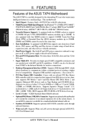
FEATURES (Motherboard Parts) II. FEATURES Parts of the ASUS TXP4 Motherboard Super Multi-I/O 3 ISA Slots 4 PCI Slots IDE Connectors AT Power Connector ATX Power Programmable Flash ROM PS/2 Mouse, USB, IrDA Serial, Parallel, Floppy 4 SIMM Sockets 2 DIMM Sockets Intel's 430TX PCIset CPU ZIF Socket 7 "Cool" Switching Voltage Regulators 512KB Pipelined Burst L2 Cache ASUS TXP4 User's Manual 11 II.
FEATURES (Motherboard Parts) II. FEATURES Parts of the ASUS TXP4 Motherboard Super Multi-I/O 3 ISA Slots 4 PCI Slots IDE Connectors AT Power Connector ATX Power Programmable Flash ROM PS/2 Mouse, USB, IrDA Serial, Parallel, Floppy 4 SIMM Sockets 2 DIMM Sockets Intel's 430TX PCIset CPU ZIF Socket 7 "Cool" Switching Voltage Regulators 512KB Pipelined Burst L2 Cache ASUS TXP4 User's Manual 11 II.
TXP4 User Manual
Page 12
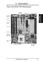
... Write ISA Slot 3 Intel PIIX4 PCIset 512KB PB L2 Cache FS2 FS1 FS0 CPU Fan Clock Freq CPU ZIF Socket 7 Switching Voltage Regulators Freq. INSTALLATION (Motherboard Layout) Row 0 1 0 1 2 3 2 3 Row 1 0 3 2 Intel 430TX PCIset Keyboard COM 2 ASUS TXP4 User's Manual COM 1 Serial Ports III. Ratio CPU Voltage RTC Clear BF2 BF1 VID2 BF0 VID1 VID0...
... Write ISA Slot 3 Intel PIIX4 PCIset 512KB PB L2 Cache FS2 FS1 FS0 CPU Fan Clock Freq CPU ZIF Socket 7 Switching Voltage Regulators Freq. INSTALLATION (Motherboard Layout) Row 0 1 0 1 2 3 2 3 Row 1 0 3 2 Intel 430TX PCIset Keyboard COM 2 ASUS TXP4 User's Manual COM 1 Serial Ports III. Ratio CPU Voltage RTC Clear BF2 BF1 VID2 BF0 VID1 VID0...
TXP4 User Manual
Page 13
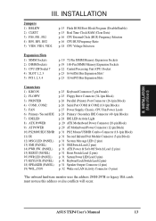
... Selection p. 16 CPU:BUS Frequency Ratio p. 18 CPU Voltage Selection Expansion Slots 1) SIMM Sockets 2) DIMM Sockets 3) CPU ZIF Socket 7 4) SLOT 1, 2, 3 5) PCI 1, 2, 3, 4 p. 19 72-Pin SIMM Memory Expansion Sockets p. 19 168-Pin DIMM Memory Expansion Sockets p. 22 Central Processing Unit (CPU) Socket p. 23 16-bit ISA Bus Expansion Slots* p. 23 32-bit PCI Bus Expansion Slots... (3-pins) *The onboard hardware monitor uses the address 290H-297H so legacy ISA cards must not use this address or else conflicts will occur. ASUS TXP4 User's Manual 13 INSTALLATION (Map of Board) III. III.
... Selection p. 16 CPU:BUS Frequency Ratio p. 18 CPU Voltage Selection Expansion Slots 1) SIMM Sockets 2) DIMM Sockets 3) CPU ZIF Socket 7 4) SLOT 1, 2, 3 5) PCI 1, 2, 3, 4 p. 19 72-Pin SIMM Memory Expansion Sockets p. 19 168-Pin DIMM Memory Expansion Sockets p. 22 Central Processing Unit (CPU) Socket p. 23 16-bit ISA Bus Expansion Slots* p. 23 32-bit PCI Bus Expansion Slots... (3-pins) *The onboard hardware monitor uses the address 290H-297H so legacy ISA cards must not use this address or else conflicts will occur. ASUS TXP4 User's Manual 13 INSTALLATION (Map of Board) III. III.
TXP4 User Manual
Page 19
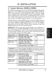
..., 128, 256MB 168-pin SDRAM or EDO DIMM (SIMM Sockets must be used when the SIMM sockets are used . INSTALLATION (System Memory) III. INSTALLATION 2. SIMMs must be unstable. The SIMMs can be empty) Total System Memory (Max 256MB) Total Memory x1 x1 = ASUS TXP4 User's Manual 19 One side (with memory chips) of the...
..., 128, 256MB 168-pin SDRAM or EDO DIMM (SIMM Sockets must be used when the SIMM sockets are used . INSTALLATION (System Memory) III. INSTALLATION 2. SIMMs must be unstable. The SIMMs can be empty) Total System Memory (Max 256MB) Total Memory x1 x1 = ASUS TXP4 User's Manual 19 One side (with memory chips) of the...
TXP4 User Manual
Page 20
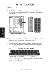
...Clip 72 Pin DRAM in only one orientation as shown because the plastic safety tab on one end of the SIMM sockets requires the notched end of the support clips. 20 ASUS TXP4 User's Manual The plastic guides should go through the two mounting holes and the support clips should snap. The SIMM... memory modules will fit in SIMM Socket Plastic Safety Tab (This Side Only) Mounting Hole To release the memory module, push ...
...Clip 72 Pin DRAM in only one orientation as shown because the plastic safety tab on one end of the SIMM sockets requires the notched end of the support clips. 20 ASUS TXP4 User's Manual The plastic guides should go through the two mounting holes and the support clips should snap. The SIMM... memory modules will fit in SIMM Socket Plastic Safety Tab (This Side Only) Mounting Hole To release the memory module, push ...
TXP4 User Manual
Page 21
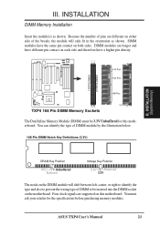
...module will only fit in the orientation as shown. Four clock signals are different on the motherboard. You must be inserted into the DIMM socket on either side of the breaks, the module will shift between left, center, or right to identify the type and also to prevent... Notch Key Definitions (3.3V) III. R 20 Pins 60 Pins 88 Pins Lock TXP4 168 Pin DIMM Memory Sockets The Dual Inline Memory Module (DIMM) must ask your retailer for this motherboard. DIMM Socket 2 DIMM Socket 1 III. ASUS TXP4 User's Manual 21 You can identify the type of pins are supported on both sides...
...module will only fit in the orientation as shown. Four clock signals are different on the motherboard. You must be inserted into the DIMM socket on either side of the breaks, the module will shift between left, center, or right to identify the type and also to prevent... Notch Key Definitions (3.3V) III. R 20 Pins 60 Pins 88 Pins Lock TXP4 168 Pin DIMM Memory Sockets The Dual Inline Memory Module (DIMM) must ask your retailer for this motherboard. DIMM Socket 2 DIMM Socket 1 III. ASUS TXP4 User's Manual 21 You can identify the type of pins are supported on both sides...
TXP4 User Manual
Page 22
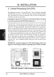
... cause damage to prevent overheating. III. With the added weight of the CPU with Pentium Processor 22 ASUS TXP4 User's Manual Use the notched corner of the CPU fan, no force is missing from the socket then upwards to BUS Frequency Ratio" and jumpers for three of pin holes and a "1" printed on the...
... cause damage to prevent overheating. III. With the added weight of the CPU with Pentium Processor 22 ASUS TXP4 User's Manual Use the notched corner of the CPU fan, no force is missing from the socket then upwards to BUS Frequency Ratio" and jumpers for three of pin holes and a "1" printed on the...


