
TX97-XE User Manual
Page 1
R TX97-XE Pentium® ATX Motherboard USER'S MANUAL
R TX97-XE Pentium® ATX Motherboard USER'S MANUAL
TX97-XE User Manual
Page 4
...14 Jumper Settings 15 Compatible Cyrix CPU Identification 18 2. Central Processing Unit (CPU 22 4. FEATURES 8 Features of the ASUS TX97-XE Motherboard 8 ASUS TX97 Smart Series Motherboards 9 Parts of Power Management Setup 47 4 ASUS TX97-XE User's Manual INSTALLATION 12 ASUS TX97-XE Motherboard Layout 12 Installation Steps 14 1. INTRODUCTION 7 How this Manual is Organized 7 Item Checklist 7 II. System Memory ... 24 5. BIOS SOFTWARE 34 Support Software 34 Flash Memory Writer Utility 34 Main Menu 34 Managing and Updating Your Motherboard's BIOS 36 6. CONTENTS I.
...14 Jumper Settings 15 Compatible Cyrix CPU Identification 18 2. Central Processing Unit (CPU 22 4. FEATURES 8 Features of the ASUS TX97-XE Motherboard 8 ASUS TX97 Smart Series Motherboards 9 Parts of Power Management Setup 47 4 ASUS TX97-XE User's Manual INSTALLATION 12 ASUS TX97-XE Motherboard Layout 12 Installation Steps 14 1. INTRODUCTION 7 How this Manual is Organized 7 Item Checklist 7 II. System Memory ... 24 5. BIOS SOFTWARE 34 Support Software 34 Flash Memory Writer Utility 34 Main Menu 34 Managing and Updating Your Motherboard's BIOS 36 6. CONTENTS I.

TX97-XE User Manual
Page 7
... II. IV. Support Software Information on the included support software Audio Installation Audio driver installation (with online help (optional) ASUS TX97-XE User's Manual 7 If you discover damaged or missing items, please contact your retailer. (1) ASUS Motherboard (1) IDE ribbon cable for master and slave drives (1) Floppy ribbon cable for (1) 5.25inch floppy and (2) 3.5inch floppies (1) Bag...
... II. IV. Support Software Information on the included support software Audio Installation Audio driver installation (with online help (optional) ASUS TX97-XE User's Manual 7 If you discover damaged or missing items, please contact your retailer. (1) ASUS Motherboard (1) IDE ribbon cable for master and slave drives (1) Floppy ribbon cable for (1) 5.25inch floppy and (2) 3.5inch floppies (1) Bag...
TX97-XE User Manual
Page 8
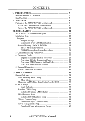
... DIMM sockets to support 8-128MB 168-pin 3.3Volt SDRAM/EDO memory modules up to 256MB. FEATURES Features of the ASUS TX97-XE Motherboard The ASUS TX97-XE is carefully designed for wireless interface. 8 ASUS TX97-XE User's Manual FEATURES Features II. This motherboard: • Intel Chipset: Features Intel's 430TX PCIset with I /O: Provides two high-speed UART-compatible serial ports and one...
... DIMM sockets to support 8-128MB 168-pin 3.3Volt SDRAM/EDO memory modules up to 256MB. FEATURES Features of the ASUS TX97-XE Motherboard The ASUS TX97-XE is carefully designed for wireless interface. 8 ASUS TX97-XE User's Manual FEATURES Features II. This motherboard: • Intel Chipset: Features Intel's 430TX PCIset with I /O: Provides two high-speed UART-compatible serial ports and one...

TX97-XE User Manual
Page 9
...from PCI master busses to memory to 528MB/s max using SDRAM. • Double the IDE Transfer Speed - II. ASUS TX97 smart series motherboards support the new generation memory - The best of Windows 95 must be used. • PC '97 Compliant -... NT. ACPI provide more Energy Saving Features for RPM and failure. FEATURES TX97 Series II. ASUS TX97-XE User's Manual 9 FEATURES ASUS TX97 Smart Series Motherboards Performance • SDRAM Optimized Performance - ASUS TX97 smart series motherboards with optional LM78/75 Hardware Monitor only) • Fan Status Monitoring and...
...from PCI master busses to memory to 528MB/s max using SDRAM. • Double the IDE Transfer Speed - II. ASUS TX97 smart series motherboards support the new generation memory - The best of Windows 95 must be used. • PC '97 Compliant -... NT. ACPI provide more Energy Saving Features for RPM and failure. FEATURES TX97 Series II. ASUS TX97-XE User's Manual 9 FEATURES ASUS TX97 Smart Series Motherboards Performance • SDRAM Optimized Performance - ASUS TX97 smart series motherboards with optional LM78/75 Hardware Monitor only) • Fan Status Monitoring and...

TX97-XE User Manual
Page 10
... operating systems such as Windows 95, Windows NT, and OS/2, require much more critical for more efficiently. • Virus Write Protection - ASUS TX97 series of two states, one is Sleep mode and the other is usually unprotected. The CPU utilization will prevent CPU damage from anywhere in ...will warn the user before the system resources are monitored to ensure stable current to the user. 10 ASUS TX97-XE User's Manual When the power button is in one of motherboards were designed to cooperate with BIOS, chipset, and flash EPROM to disable write permission when the system's ...
... operating systems such as Windows 95, Windows NT, and OS/2, require much more critical for more efficiently. • Virus Write Protection - ASUS TX97 series of two states, one is Sleep mode and the other is usually unprotected. The CPU utilization will prevent CPU damage from anywhere in ...will warn the user before the system resources are monitored to ensure stable current to the user. 10 ASUS TX97-XE User's Manual When the power button is in one of motherboards were designed to cooperate with BIOS, chipset, and flash EPROM to disable write permission when the system's ...

TX97-XE User Manual
Page 11
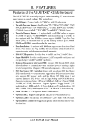
FEATURES Motherboard Parts II. COM 2 Intel's 430TX PCIset (Optional) T:Joystick/Midi B:Out/In/Mic 4 PCI Slots 4 SIMM Sockets 2 DIMM Sockets CPU ZIF CPU Thermal Socket 7 Sensor (optional) 512KB Pipelined Burst L2 Cache Creative Labs Audio (optional) 4 ISA Slots LM78 Hardware Programmable Monitor (optional) Flash ROM ASUS TX97-XE User's Manual 11 B: Serial Conn. II. FEATURES Parts of the ASUS TX97-XE Motherboard T: PS/2 Mouse B: PS/2 Keyboard T: USB Port 1 B: USB Port 2 COM 1 T: Parallel Conn.
FEATURES Motherboard Parts II. COM 2 Intel's 430TX PCIset (Optional) T:Joystick/Midi B:Out/In/Mic 4 PCI Slots 4 SIMM Sockets 2 DIMM Sockets CPU ZIF CPU Thermal Socket 7 Sensor (optional) 512KB Pipelined Burst L2 Cache Creative Labs Audio (optional) 4 ISA Slots LM78 Hardware Programmable Monitor (optional) Flash ROM ASUS TX97-XE User's Manual 11 B: Serial Conn. II. FEATURES Parts of the ASUS TX97-XE Motherboard T: PS/2 Mouse B: PS/2 Keyboard T: USB Port 1 B: USB Port 2 COM 1 T: Parallel Conn.
TX97-XE User Manual
Page 12
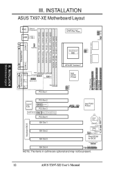
... module) SIMM Socket 2 (32-bit, 72-pin module) SIMM Socket 3 (32-bit, 72-pin module) SIMM Socket 4 (32-bit, 72-pin module) III. INSTALLATION Motherboard Layout III. INSTALLATION ASUS TX97-XE Motherboard Layout COM 1 PS/2 T: Mouse B: Keyboard USB T: USB 1 B: USB 2 FANPWR3 Board Power Input for BIOS Infrared Con. (IrDA) ISA Slot 4 Panel Connections IDE LED...
... module) SIMM Socket 2 (32-bit, 72-pin module) SIMM Socket 3 (32-bit, 72-pin module) SIMM Socket 4 (32-bit, 72-pin module) III. INSTALLATION Motherboard Layout III. INSTALLATION ASUS TX97-XE Motherboard Layout COM 1 PS/2 T: Mouse B: Keyboard USB T: USB 1 B: USB 2 FANPWR3 Board Power Input for BIOS Infrared Con. (IrDA) ISA Slot 4 Panel Connections IDE LED...
TX97-XE User Manual
Page 13
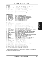
..., 2, 3 p. 29 1Chassis,2CPU,3PowerSupplyFanPowerLead(3-pinBlock) 12) CHASSIS p. 29 Chassis Open Alarm Lead (4-1pin Block) 13) IR p. 30 Infrared Port Module Connector 14) ATXPWR p. 30 ATX Motherboard Power Connector (20-pin Block) 15) VOLCTL (optional) p. 31 Digital Volume Level Control (5-pin Block) 16) WOL p. 31 Wake on LAN (3 pins) 17) MSG LED... Connector (4 pins) *The onboard hardware monitor uses the address 290H-297H so legacy ISA cards must not use this address or else conflicts will occur. ASUS TX97-XE User's Manual 13 INSTALLATION Map of Board III.
..., 2, 3 p. 29 1Chassis,2CPU,3PowerSupplyFanPowerLead(3-pinBlock) 12) CHASSIS p. 29 Chassis Open Alarm Lead (4-1pin Block) 13) IR p. 30 Infrared Port Module Connector 14) ATXPWR p. 30 ATX Motherboard Power Connector (20-pin Block) 15) VOLCTL (optional) p. 31 Digital Volume Level Control (5-pin Block) 16) WOL p. 31 Wake on LAN (3 pins) 17) MSG LED... Connector (4 pins) *The onboard hardware monitor uses the address 290H-297H so legacy ISA cards must not use this address or else conflicts will occur. ASUS TX97-XE User's Manual 13 INSTALLATION Map of Board III.

TX97-XE User Manual
Page 14
..., and Power Supply 6. The jumper settings will also be sharing pins from the system. 14 ASUS TX97-XE User's Manual The jumpers will be moved together. For manufacturing simplicity, the jump- Unplug your computer, you work on the motherboard. Use a grounded wrist strap before handling computer components. Hold components by the edges and try...
..., and Power Supply 6. The jumper settings will also be sharing pins from the system. 14 ASUS TX97-XE User's Manual The jumpers will be moved together. For manufacturing simplicity, the jump- Unplug your computer, you work on the motherboard. Use a grounded wrist strap before handling computer components. Hold components by the edges and try...
TX97-XE User Manual
Page 15
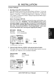
...) Clear Data 2. Onboard Audio Enabled Disabled AUDIO [2-3] (Default) [1-2] AUDIO 1 2 3 Disable AUDIO 1 2 3 Enable (Default) Onboard Audio (Disable / Enable) ASUS TX97-XE User's Manual 15 You should enter BIOS to use your own audio card. Onboard Audio Selection (AUDIO) (with optional onboard Audio) This jumper allows you... reapplying this action. Battery Test Jumper (RTCLR) You can test the battery's current by this jumper. Otherwise, leave on your motherboard. Real Time Clock (RTC) RAM (RTCLR) The CMOS RAM is no power to your computer, (5) Hold down during bootup ...
...) Clear Data 2. Onboard Audio Enabled Disabled AUDIO [2-3] (Default) [1-2] AUDIO 1 2 3 Disable AUDIO 1 2 3 Enable (Default) Onboard Audio (Disable / Enable) ASUS TX97-XE User's Manual 15 You should enter BIOS to use your own audio card. Onboard Audio Selection (AUDIO) (with optional onboard Audio) This jumper allows you... reapplying this action. Battery Test Jumper (RTCLR) You can test the battery's current by this jumper. Otherwise, leave on your motherboard. Real Time Clock (RTC) RAM (RTCLR) The CMOS RAM is no power to your computer, (5) Hold down during bootup ...

TX97-XE User Manual
Page 17
... 6x86-P166+ with the Cyrix PR166+ installed on this motherboard. III. III. INSTALLATION Set the jumpers by the Internal... 60MHz 50MHz (BUS Freq.) FS2 FS1 FS0 [2-3] [1-2] [2-3] [2-3] [1-2] [2-3] [2-3] [1-2] [2-3] [2-3] [2-3] [1-2] [2-3] [1-2] [2-3] [2-3] [2-3] [1-2] [2-3] [1-2] [2-3] [2-3] [2-3] [1-2] [2-3] [2-3] [2-3] (Freq. INSTALLATION Jumpers ASUS TX97-XE User's Manual 17 Ratio) BF1 BF0 [1-2] [1-2] [2-3] [1-2] [2-3] [2-3] [2-3] [2-3] [1-2] [2-3] [1-2] [2-3] [1-2] [1-2] [1-2] [1-2] [1-2] [1-2] AMD-K6-PR233 AMD-K6-PR200 AMD-K6-PR166 233MHz 3.5x 200MHz 3.0x 166MHz 2.5x...
... 6x86-P166+ with the Cyrix PR166+ installed on this motherboard. III. III. INSTALLATION Set the jumpers by the Internal... 60MHz 50MHz (BUS Freq.) FS2 FS1 FS0 [2-3] [1-2] [2-3] [2-3] [1-2] [2-3] [2-3] [1-2] [2-3] [2-3] [2-3] [1-2] [2-3] [1-2] [2-3] [2-3] [2-3] [1-2] [2-3] [1-2] [2-3] [2-3] [2-3] [1-2] [2-3] [2-3] [2-3] (Freq. INSTALLATION Jumpers ASUS TX97-XE User's Manual 17 Ratio) BF1 BF0 [1-2] [1-2] [2-3] [1-2] [2-3] [2-3] [2-3] [2-3] [1-2] [2-3] [1-2] [2-3] [1-2] [1-2] [1-2] [1-2] [1-2] [1-2] AMD-K6-PR233 AMD-K6-PR200 AMD-K6-PR166 233MHz 3.5x 200MHz 3.0x 166MHz 2.5x...

TX97-XE User Manual
Page 18
...Selection (VID0, 1, 2, 3) These jumpers set the voltage supplied to [2-3] or [----] (removed) will result in the same voltages respectively. 1 2 3 2.5 Volts 18 ASUS TX97-XE User's Manual VID1 for 3.4V(STD) is labeled Cyrix 6x86 PR166+ but must be true for the serial number. Because CPU designs change rapidly, the... CPU and follow the Voltage setting diagramed below the chart. Look for both 3.4V(STD) and 2.8V(Dual). Look on this motherboard is ignored, therefore, the jumper setting for 2.8V(Dual) may work for the CPU voltage included with your CPU. Manufacturer CPU ...
...Selection (VID0, 1, 2, 3) These jumpers set the voltage supplied to [2-3] or [----] (removed) will result in the same voltages respectively. 1 2 3 2.5 Volts 18 ASUS TX97-XE User's Manual VID1 for 3.4V(STD) is labeled Cyrix 6x86 PR166+ but must be true for the serial number. Because CPU designs change rapidly, the... CPU and follow the Voltage setting diagramed below the chart. Look for both 3.4V(STD) and 2.8V(Dual). Look on this motherboard is ignored, therefore, the jumper setting for 2.8V(Dual) may work for the CPU voltage included with your CPU. Manufacturer CPU ...

TX97-XE User Manual
Page 19
.... IMPORTANT: Memory speed setup is required through "Auto Configuration" in pairs so that each Row (see Map of Motherboard for 3.3Volt (power level) Unbuffered Synchronous DRAMs (SDRAM) or EDO DRAM of the memory subsystem and will burn your... else you will be installed in BIOS Chipset Setup of the DIMM module takes up half a Row on the motherboard. Mixing SIMMs and DIMMs require 5.0Volt (signal level) tolerant memory chips which are not supported). One side (... must be empty) Total System Memory (Max 256MB) Total Memory x1 x1 = ASUS TX97-XE User's Manual 19 INSTALLATION 2.
.... IMPORTANT: Memory speed setup is required through "Auto Configuration" in pairs so that each Row (see Map of Motherboard for 3.3Volt (power level) Unbuffered Synchronous DRAMs (SDRAM) or EDO DRAM of the memory subsystem and will burn your... else you will be installed in BIOS Chipset Setup of the DIMM module takes up half a Row on the motherboard. Mixing SIMMs and DIMMs require 5.0Volt (signal level) tolerant memory chips which are not supported). One side (... must be empty) Total System Memory (Max 256MB) Total Memory x1 x1 = ASUS TX97-XE User's Manual 19 INSTALLATION 2.

TX97-XE User Manual
Page 21
... Pins Lock The Dual Inline Memory Module (DIMM) memory module must ask your retailer for this motherboard. III. SDRAM DIMM modules have a higher pin density. INSTALLATION DIMM Memory Installation Procedures Insert the module as shown. ASUS TX97-XE User's Manual 21 DRAM SIMM modules have the same pin contact on each side and therefore...
... Pins Lock The Dual Inline Memory Module (DIMM) memory module must ask your retailer for this motherboard. III. SDRAM DIMM modules have a higher pin density. INSTALLATION DIMM Memory Installation Procedures Insert the module as shown. ASUS TX97-XE User's Manual 21 DRAM SIMM modules have the same pin contact on each side and therefore...

TX97-XE User Manual
Page 22
INSTALLATION 3. If this is backwards compatible with the motherboard should point towards the end the of this section.) To install a CPU, first turn off your system and remove its cover. Insert the CPU with Pentium MMX Processor 22 ASUS TX97-XE User's Manual With the added weight of pin holes ...from that corner. The picture is missing from the socket then upwards to prevent overheating. you install. Central Processing Unit (CPU) The motherboard provides a 321-pin ZIF Socket 7 that will only fit in the one hole is for "BUS Frequency Selection" depending on the CPU...
INSTALLATION 3. If this is backwards compatible with the motherboard should point towards the end the of this section.) To install a CPU, first turn off your system and remove its cover. Insert the CPU with Pentium MMX Processor 22 ASUS TX97-XE User's Manual With the added weight of pin holes ...from that corner. The picture is missing from the socket then upwards to prevent overheating. you install. Central Processing Unit (CPU) The motherboard provides a 321-pin ZIF Socket 7 that will only fit in the one hole is for "BUS Frequency Selection" depending on the CPU...

TX97-XE User Manual
Page 23
... necessary jumpers on the slot with the screw you unplug your motherboard and expansion cards. Expansion Card Installation Procedure: 1. INSTALLATION 4. You may cause severe damage to both your power supply when adding or removing expansion cards or other system components. ASUS TX97-XE User's Manual 23 Edit the BIOS settings if necessary. (such as...
... necessary jumpers on the slot with the screw you unplug your motherboard and expansion cards. Expansion Card Installation Procedure: 1. INSTALLATION 4. You may cause severe damage to both your power supply when adding or removing expansion cards or other system components. ASUS TX97-XE User's Manual 23 Edit the BIOS settings if necessary. (such as...

TX97-XE User Manual
Page 24
... PCI cards are handled the same way as the IRQ assignment process described earlier. INSTALLATION Expansion Cards 24 ASUS TX97-XE User's Manual Since all the PCI slots on this motherboard has complied with the BIOS, you can select a DMA channel in it that the jumpers on your ...from those used to indicate which was developed to allow automatic system configuration whenever a PNP-compliant card is automatically assigned to use this motherboard are set something called the INT (interrupt) assignment. For older Legacy cards that has a card in the PCI and PnP configuration ...
... PCI cards are handled the same way as the IRQ assignment process described earlier. INSTALLATION Expansion Cards 24 ASUS TX97-XE User's Manual Since all the PCI slots on this motherboard has complied with the BIOS, you can select a DMA channel in it that the jumpers on your ...from those used to indicate which was developed to allow automatic system configuration whenever a PNP-compliant card is automatically assigned to use this motherboard are set something called the INT (interrupt) assignment. For older Legacy cards that has a card in the PCI and PnP configuration ...

TX97-XE User Manual
Page 25
INSTALLATION 5. Placing jumper caps over these will direct IRQ12 to your motherboard. IDE ribbon cable must be connected with the second drive connector no more than 6in. (15cm) from jumpers in BIOS Features Setup of the ...: Ribbon cables should always be less than 18in. (46cm), with the red stripe on standard AT keyboards. PS/2 Mouse (6-pin Female) ASUS TX97-XE User's Manual 25 The four corners of the Motherboard." PS/2 Keyboard (6-pin Female) 2. INSTALLATION DCMoAnnCehcatnornsels III. These are used for a standard keyboard using an PS/2 plug (mini DIN). Pin 1...
INSTALLATION 5. Placing jumper caps over these will direct IRQ12 to your motherboard. IDE ribbon cable must be connected with the second drive connector no more than 6in. (15cm) from jumpers in BIOS Features Setup of the ...: Ribbon cables should always be less than 18in. (46cm), with the red stripe on standard AT keyboards. PS/2 Mouse (6-pin Female) ASUS TX97-XE User's Manual 25 The four corners of the Motherboard." PS/2 Keyboard (6-pin Female) 2. INSTALLATION DCMoAnnCehcatnornsels III. These are used for a standard keyboard using an PS/2 plug (mini DIN). Pin 1...

TX97-XE User Manual
Page 29
... for an open alarm feature to work, you must have the LM78 hardware monitor (optional) onboard and connect a sensor or switch to the motherboard and/or the CPU fan if these pins. Chassis , CPU , & Power Supply Fan Connectors (3-pin FANPWR) These connectors support cooling fans ...consideration the polarity of 500mAMP (6WATT) or less. Rotation +12V GND R R Chassis Open Alarm Lead Power supply standby +5V Ground Chassis Signal ASUS TX97-XE User's Manual 29 Chassis Open Alarm Lead (4-1pin CHASSIS) This lead is no airflow across the onboard heat sink(s) instead of the expansion slots...
... for an open alarm feature to work, you must have the LM78 hardware monitor (optional) onboard and connect a sensor or switch to the motherboard and/or the CPU fan if these pins. Chassis , CPU , & Power Supply Fan Connectors (3-pin FANPWR) These connectors support cooling fans ...consideration the polarity of 500mAMP (6WATT) or less. Rotation +12V GND R R Chassis Open Alarm Lead Power supply standby +5V Ground Chassis Signal ASUS TX97-XE User's Manual 29 Chassis Open Alarm Lead (4-1pin CHASSIS) This lead is no airflow across the onboard heat sink(s) instead of the expansion slots...


