TX97-LE User Manual
Page 1
R TX97-LE Pentium® Motherboard USER'S MANUAL
R TX97-LE Pentium® Motherboard USER'S MANUAL

TX97-LE User Manual
Page 2
... their respective companies, and are used only for each product design represented by the digit before and after the period of the manual revision number. All Rights Reserved. Product Name: ASUS TX97-LE Manual Revision: 1.00 Release Date: January 1998 2 ASUS TX97-LE User's Manual The product name and revision number are represented by the third digit in the...
... their respective companies, and are used only for each product design represented by the digit before and after the period of the manual revision number. All Rights Reserved. Product Name: ASUS TX97-LE Manual Revision: 1.00 Release Date: January 1998 2 ASUS TX97-LE User's Manual The product name and revision number are represented by the third digit in the...

TX97-LE User Manual
Page 3
... Support Fax: +886-2-2895-9254 BBS: +886-2-2896-4667 Email: tsd@asus.com.tw WWW: www.asus.com.tw Gopher: gopher.asus.com.tw FTP: ftp.asus.com.tw/pub/ASUS ASUS COMPUTER INTERNATIONAL Marketing Info Address: 721 Charcot Avenue, San Jose, CA 95131,...asus.com.tw WWW: www.asus.com ASUS COMPUTER GmbH Marketing Info Address: Harkort Str. 25, 40880 Ratingen, BRD, Germany Telephone: 49-2102-445011 Fax: 49-2102-442066 Email: info-ger@asus.com.tw Technical Support BBS: 49-2102-448690 Email: tsd-ger@asus.com.tw Hotline: 49-2102-499712 ASUS TX97-LE User's Manual 3 ASUS...
... Support Fax: +886-2-2895-9254 BBS: +886-2-2896-4667 Email: tsd@asus.com.tw WWW: www.asus.com.tw Gopher: gopher.asus.com.tw FTP: ftp.asus.com.tw/pub/ASUS ASUS COMPUTER INTERNATIONAL Marketing Info Address: 721 Charcot Avenue, San Jose, CA 95131,...asus.com.tw WWW: www.asus.com ASUS COMPUTER GmbH Marketing Info Address: Harkort Str. 25, 40880 Ratingen, BRD, Germany Telephone: 49-2102-445011 Fax: 49-2102-442066 Email: info-ger@asus.com.tw Technical Support BBS: 49-2102-448690 Email: tsd-ger@asus.com.tw Hotline: 49-2102-499712 ASUS TX97-LE User's Manual 3 ASUS...

TX97-LE User Manual
Page 4
CONTENTS I. FEATURES 8 Features of the ASUS TX97-LE Motherboard 8 Introduction to ASUS Smart Series of motherboards 9 Parts of Chipset Features Setup 43 4 ASUS TX97-LE User's Manual INSTALLATION 12 ASUS TX97-LE Motherboard Layout 12 Installation Steps 14 1. System Memory (SIMM & DIMM 19 SIMM Memory Installation ... CMOS Setup 38 BIOS Features Setup 41 Details of BIOS Features Setup 41 Chipset Features Setup 43 Details of the ASUS TX97-LE Motherboard 11 III. Jumpers 14 Jumper Settings 15 Compatible Cyrix CPU Identification 18 2. Central Processing Unit (CPU 22 ...
CONTENTS I. FEATURES 8 Features of the ASUS TX97-LE Motherboard 8 Introduction to ASUS Smart Series of motherboards 9 Parts of Chipset Features Setup 43 4 ASUS TX97-LE User's Manual INSTALLATION 12 ASUS TX97-LE Motherboard Layout 12 Installation Steps 14 1. System Memory (SIMM & DIMM 19 SIMM Memory Installation ... CMOS Setup 38 BIOS Features Setup 41 Details of BIOS Features Setup 41 Chipset Features Setup 43 Details of the ASUS TX97-LE Motherboard 11 III. Jumpers 14 Jumper Settings 15 Compatible Cyrix CPU Identification 18 2. Central Processing Unit (CPU 22 ...

TX97-LE User Manual
Page 5
... 59 Setting Up the ASUS PCI-SC200 & PCI-SC860 60 Setting the INT Assignment for the ASUS PCI-SC200 60 Terminator Requirements for SCSI Devices 60 Terminator Settings for the ASUS PCI-SC860 61 Terminator Settings for the ASUS PCI-SC200 61 SCSI...ASUS Smart Motherboard Support CD 3.10 55 Desktop Management Interface (DMI 56 Introducing the ASUS DMI Configuration Utility 56 System Requirements 56 Using the ASUS DMI Configuration Utility 57 VI. ASUS LAN Card 63 ASUS PCI-L101 Fast Ethernet Card 63 Features 64 Software Driver Support 64 Question and Answer 64 ASUS TX97-LE User's Manual...
... 59 Setting Up the ASUS PCI-SC200 & PCI-SC860 60 Setting the INT Assignment for the ASUS PCI-SC200 60 Terminator Requirements for SCSI Devices 60 Terminator Settings for the ASUS PCI-SC860 61 Terminator Settings for the ASUS PCI-SC200 61 SCSI...ASUS Smart Motherboard Support CD 3.10 55 Desktop Management Interface (DMI 56 Introducing the ASUS DMI Configuration Utility 56 System Requirements 56 Using the ASUS DMI Configuration Utility 57 VI. ASUS LAN Card 63 ASUS PCI-L101 Fast Ethernet Card 63 Features 64 Software Driver Support 64 Question and Answer 64 ASUS TX97-LE User's Manual...

TX97-LE User Manual
Page 6
... a Class B digital device, pursuant to an outlet on , the user is encouraged to try to correct the interference by one or more of Communications. 6 ASUS TX97-LE User's Manual Operation is required to assure compliance with the limits for radio noise emissions from that interference will not occur in a residential installation. The use of...
... a Class B digital device, pursuant to an outlet on , the user is encouraged to try to correct the interference by one or more of Communications. 6 ASUS TX97-LE User's Manual Operation is required to assure compliance with the limits for radio noise emissions from that interference will not occur in a residential installation. The use of...

TX97-LE User Manual
Page 7
Features: Information and specifications concerning this manual is organized This manual is complete. Introduction: Manual information and checklist II. Support Software: Information on -LAN 10/100 Ethernet Card (optional) ASUS TX97-LE User's Manual 7 If you discover damaged or missing items, please contact your package is divided into the following sections: I. I . BIOS Software: Instructions on setting up the...
Features: Information and specifications concerning this manual is organized This manual is complete. Introduction: Manual information and checklist II. Support Software: Information on -LAN 10/100 Ethernet Card (optional) ASUS TX97-LE User's Manual 7 If you discover damaged or missing items, please contact your package is divided into the following sections: I. I . BIOS Software: Instructions on setting up the...

TX97-LE User Manual
Page 8
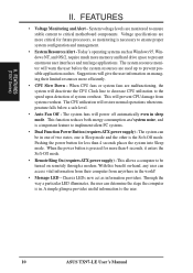
... one parallel port with two DIMM sockets to the Infrared Module for wireless connections. • Desktop Management Interface (DMI): Supports DMI through optional ASUS PCIL101 Fast Ethernet card. 8 ASUS TX97-LE User's Manual SIMMs and DIMMs cannot be directed from COM2 to support 8-256MB 168-pin 3.3Volt SDRAM/EDO memory modules up . • Level 2 Cache...
... one parallel port with two DIMM sockets to the Infrared Module for wireless connections. • Desktop Management Interface (DMI): Supports DMI through optional ASUS PCIL101 Fast Ethernet card. 8 ASUS TX97-LE User's Manual SIMMs and DIMMs cannot be directed from COM2 to support 8-256MB 168-pin 3.3Volt SDRAM/EDO memory modules up . • Level 2 Cache...

TX97-LE User Manual
Page 9
...system components, and 32-bit device drivers and installation procedures for RPM and failure. Both the BIOS and hardware levels of ASUS TX97 series of motherboards sup- To prevent system overheat and system damage, the CPU fan and system fans are based on the... are monitored for both Windows 95 and Windows NT. FEATURES (Smart Series) II. ASUS TX97-LE User's Manual 9 The best of Windows 95 must be ready around the clock everyday, yet satisfy all ASUS 430TX series of motherboards Performance • SDRAM Optimized Performance - Intelligence: (with existing ATA...
...system components, and 32-bit device drivers and installation procedures for RPM and failure. Both the BIOS and hardware levels of ASUS TX97 series of motherboards sup- To prevent system overheat and system damage, the CPU fan and system fans are based on the... are monitored for both Windows 95 and Windows NT. FEATURES (Smart Series) II. ASUS TX97-LE User's Manual 9 The best of Windows 95 must be ready around the clock everyday, yet satisfy all ASUS 430TX series of motherboards Performance • SDRAM Optimized Performance - Intelligence: (with existing ATA...
TX97-LE User Manual
Page 10
The system fans will restore normal operations when temperature falls below a safe level. • Auto Fan Off - FEATURES (TX97 Series) II. When the power button is pressed for more critical for less than 4 seconds, it enters the Soft-Off mode. • ...system will give the user information on -hand, any user can determine the stage the computer is a important feature to the user. 10 ASUS TX97-LE User's Manual The system can be turned on remotely through a modem. The system resource monitor will prevent CPU damage from system overheat. This function reduces both...
The system fans will restore normal operations when temperature falls below a safe level. • Auto Fan Off - FEATURES (TX97 Series) II. When the power button is pressed for more critical for less than 4 seconds, it enters the Soft-Off mode. • ...system will give the user information on -hand, any user can determine the stage the computer is a important feature to the user. 10 ASUS TX97-LE User's Manual The system can be turned on remotely through a modem. The system resource monitor will prevent CPU damage from system overheat. This function reduces both...
TX97-LE User Manual
Page 11
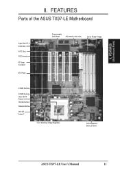
FEATURES (Motherboard Parts) II. II. FEATURES Parts of the ASUS TX97-LE Motherboard Super Multi-I/O 3 ISA Slots 4 PCI Slots IDE Connectors AT Power Connector ATX Power Programmable Flash ROM PS/2 Mouse, USB, IrDA Serial, Parallel, Floppy 4 SIMM Sockets 2 DIMM Sockets Intel's 430TX PCIset Thermal Sensors Hardware Monitor CPU ZIF Socket 7 "Cool" Switching Voltage Regulators 512KB Pipelined Burst L2 Cache ASUS TX97-LE User's Manual 11
FEATURES (Motherboard Parts) II. II. FEATURES Parts of the ASUS TX97-LE Motherboard Super Multi-I/O 3 ISA Slots 4 PCI Slots IDE Connectors AT Power Connector ATX Power Programmable Flash ROM PS/2 Mouse, USB, IrDA Serial, Parallel, Floppy 4 SIMM Sockets 2 DIMM Sockets Intel's 430TX PCIset Thermal Sensors Hardware Monitor CPU ZIF Socket 7 "Cool" Switching Voltage Regulators 512KB Pipelined Burst L2 Cache ASUS TX97-LE User's Manual 11
TX97-LE User Manual
Page 12
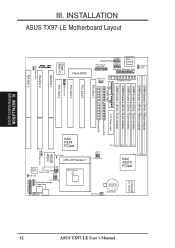
... Chasis Open Alarm Infrared IDE LED Monitor LM78 Panel Connectors Chassis Fan 12 ASUS TX97-LE User's Manual III. INSTALLATION (Motherboard Layout) Intel PIIX4 PCIset Row 0 1 0 1 2 3 2 3 Clock Freq CPU Fan Row 1 0 3 2 Intel 430TX PCIset CR2032 3V Lithium Cell BIOS Power 512KB PB L2 ...
... Chasis Open Alarm Infrared IDE LED Monitor LM78 Panel Connectors Chassis Fan 12 ASUS TX97-LE User's Manual III. INSTALLATION (Motherboard Layout) Intel PIIX4 PCIset Row 0 1 0 1 2 3 2 3 Clock Freq CPU Fan Row 1 0 3 2 Intel 430TX PCIset CR2032 3V Lithium Cell BIOS Power 512KB PB L2 ...

TX97-LE User Manual
Page 13
ASUS TX97-LE User's Manual 13 III. INSTALLATION (Map of Board) III. INSTALLATION Jumpers 1) BBLKW 2) CLRTC 3) KBPWR 4) FS0, FS1, FS2 5) BF0, BF1, BF2 6) VID0, VID1, VID2 p. 15 Flash ROM Boot ...
ASUS TX97-LE User's Manual 13 III. INSTALLATION (Map of Board) III. INSTALLATION Jumpers 1) BBLKW 2) CLRTC 3) KBPWR 4) FS0, FS1, FS2 5) BF0, BF1, BF2 6) VID0, VID1, VID2 p. 15 Flash ROM Boot ...

TX97-LE User Manual
Page 14
... components are made through the use of your computer. 1. ers may be shown as the power supply case. 3. Use the diagrams in this manual instead of jumpers. A "1" is always on top or on the board. To connect the pins, simply place a plastic jumper cap over the... to touch the IC chips, leads or connectors, or other groups. WARNING! To protect them against damage from the system. 14 ASUS TX97-LE User's Manual Jumpers Several hardware settings are separated from static electricity, you should follow some precautions whenever you must complete the following the pin layout ...
... components are made through the use of your computer. 1. ers may be shown as the power supply case. 3. Use the diagrams in this manual instead of jumpers. A "1" is always on top or on the board. To connect the pins, simply place a plastic jumper cap over the... to touch the IC chips, leads or connectors, or other groups. WARNING! To protect them against damage from the system. 14 ASUS TX97-LE User's Manual Jumpers Several hardware settings are separated from static electricity, you should follow some precautions whenever you must complete the following the pin layout ...

TX97-LE User Manual
Page 15
... off your computer, (2) Short solder points using a small metalic object, (3) Turn on your computer, (4) Hold down during bootup and enter BIOS setup to Clear Data ASUS TX97-LE User's Manual 15 INSTALLATION (Jumpers) Boot Block Programming 2. III. INSTALLATION Jumper Settings 1. Programming Disabled Enabled BBLKW [1-2] (Default) [2-3] BBLKW BBLKW R Disabled/Protect (Default) Enabled III. This is...
... off your computer, (2) Short solder points using a small metalic object, (3) Turn on your computer, (4) Hold down during bootup and enter BIOS setup to Clear Data ASUS TX97-LE User's Manual 15 INSTALLATION (Jumpers) Boot Block Programming 2. III. INSTALLATION Jumper Settings 1. Programming Disabled Enabled BBLKW [1-2] (Default) [2-3] BBLKW BBLKW R Disabled/Protect (Default) Enabled III. This is...

TX97-LE User Manual
Page 16
... Ratio equals the CPU's Internal frequency (the advertised CPU speed). 5. III. The following table is set to power up your CPU when possible. 16 ASUS TX97-LE User's Manual CPU to the instructions included with the above 66MHz exceed the specifications for general reference purposes only. Always refer to BUS Frequency Ratio (BF0, BF1...
... Ratio equals the CPU's Internal frequency (the advertised CPU speed). 5. III. The following table is set to power up your CPU when possible. 16 ASUS TX97-LE User's Manual CPU to the instructions included with the above 66MHz exceed the specifications for general reference purposes only. Always refer to BUS Frequency Ratio (BF0, BF1...

TX97-LE User Manual
Page 17
ASUS TX97-LE User's Manual 17 III. INSTALLATION FS2 FS1 FS0 FS2 FS1 FS0 FS2 FS1 FS0 FS2 FS1 FS0 FS2 FS1 FS0 FS2 FS1 FS0 R Match the table's Ratio ...
ASUS TX97-LE User's Manual 17 III. INSTALLATION FS2 FS1 FS0 FS2 FS1 FS0 FS2 FS1 FS0 FS2 FS1 FS0 FS2 FS1 FS0 FS2 FS1 FS0 R Match the table's Ratio ...
TX97-LE User Manual
Page 18
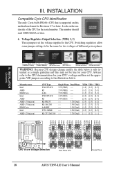
... 2.4Volts 1 1 1 1 1 2 2 2 2 2 3 3 3 3 3 2.5Volts 2.6Volts 2.7Volts 2.8Volts 2.9Volts 1 1 1 1 2 2 2 2 3 3 3 3 CPU Vcore Voltage Selection 3.0Volts 3.1Volts 3.2Volts Dual Plane CPU 3.3Volts 1 2 3 3.4V (STD) 1 2 3 3.5V (VRE) Single Plane 18 ASUS TX97-LE User's Manual Voltage Regulator Output Selection (VID0, 1, 2) These jumpers set the appropriate VID jumpers according to the CPU. INSTALLATION Compatible Cyrix CPU Identification The only Cyrix 6x86...
... 2.4Volts 1 1 1 1 1 2 2 2 2 2 3 3 3 3 3 2.5Volts 2.6Volts 2.7Volts 2.8Volts 2.9Volts 1 1 1 1 2 2 2 2 3 3 3 3 CPU Vcore Voltage Selection 3.0Volts 3.1Volts 3.2Volts Dual Plane CPU 3.3Volts 1 2 3 3.4V (STD) 1 2 3 3.5V (VRE) Single Plane 18 ASUS TX97-LE User's Manual Voltage Regulator Output Selection (VID0, 1, 2) These jumpers set the appropriate VID jumpers according to the CPU. INSTALLATION Compatible Cyrix CPU Identification The only Cyrix 6x86...
TX97-LE User Manual
Page 19
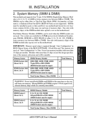
..., 32, 64, 128, 256MB 168-pin SDRAM or EDO DIMM (SIMM Sockets must be empty) Total System Memory (Max 256MB) Total Memory x1 x1 = ASUS TX97-LE User's Manual 19 Two sockets are available for row locations) contains 64-bits of the same size and type of the DIMM module takes up half a row...
..., 32, 64, 128, 256MB 168-pin SDRAM or EDO DIMM (SIMM Sockets must be empty) Total System Memory (Max 256MB) Total Memory x1 x1 = ASUS TX97-LE User's Manual 19 Two sockets are available for row locations) contains 64-bits of the same size and type of the DIMM module takes up half a row...

TX97-LE User Manual
Page 20
... one orientation as shown because the plastic safety tab on one end of the SIMM sockets requires the notched end of the support clips. 20 ASUS TX97-LE User's Manual III. The SIMM memory modules will fit in SIMM Socket Plastic Safety Tab (This Side Only) Mounting Hole To release the memory module, push...
... one orientation as shown because the plastic safety tab on one end of the SIMM sockets requires the notched end of the support clips. 20 ASUS TX97-LE User's Manual III. The SIMM memory modules will fit in SIMM Socket Plastic Safety Tab (This Side Only) Mounting Hole To release the memory module, push...


