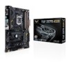
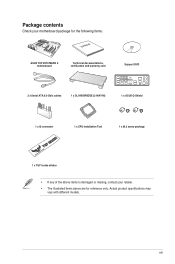
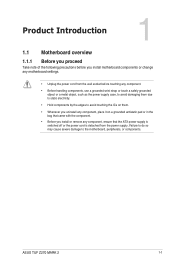
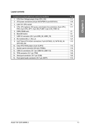
TUF Z270 MARK 2 Users manual ENGLISH
Page 13
Actual product specifications may vary with different models. Package contents Check your motherboard package for the following items: User Manual ASUS TUF Z270 MARK 2 motherboard Technical documentations, certification and warranty card Support DVD 2 x Serial ATA 6.0 Gb/s cables 1 x SLI HB BRIDGE (2-WAY-M) 1 x ASUS Q-Shield 1 x Q-connector 1 x CPU Installation Tool 1 x M.2 screw package 1 x TUF Inside sticker • If any of the above items is damaged or missing, contact your retailer. • The illustrated items above are for reference only. xiii
TUF Z270 MARK 2 Users manual ENGLISH
Page 15
... wall socket before touching any component, ensure that the ATX power supply is switched off or the power cord is detached from the power supply. ASUS TUF Z270 MARK 2 1-1 Failure to do so may cause severe damage to avoid touching the ICs on them. • Whenever you uninstall any component, place it on a grounded...
TUF Z270 MARK 2 Users manual ENGLISH
Page 17
...-1 pin USB910; USB1112) 13. USB3_78) 8. Front panel audio connector (10-1 pin AAFP) Page 1-11 1-18 1-4 1-17 1-5 1-9 1-15 1-21 1-13 1-10 1-19 1-16 1-20 1-20 1-14 ASUS TUF Z270 MARK 2 1-3
TUF Z270 MARK 2 Users manual ENGLISH
Page 19
Recommended memory configurations ASUS TUF Z270 MARK 2 1-5 DO NOT install a DDR, DDR2, or DDR3 memory module to the DDR4 slot. A DDR4 module is notched differently from a DDR, DDR2, or DDR3 module. Chapter 1 1.1.4 System memory The motherboard comes with four DDR4 (Double Data Rate 4) Quad Inline Memory Modules (DIMM) slots.
TUF Z270 MARK 2 Users manual ENGLISH
Page 21
Failure to do so may cause you physical injury and damage motherboard components. 1.1.5 Expansion slots Unplug the power cord before adding or removing expansion cards. Chapter 1 Slot No. 1 2 3 4 5 6 Slot Description PCIE 3.0/2.0 x1_1 slot PCIE 3.0/2.0 x16_1 slot PCIE 3.0/2.0 x1_2 slot PCIE 3.0/2.0 x16_2 slot PCIE 3.0/2.0 x1_3 slot PCIE 3.0/2.0 x16_3 slot ASUS TUF Z270 MARK 2 1-7
TUF Z270 MARK 2 Users manual ENGLISH
Page 23
... LEDs for the exact location of the DRAM_LED. • The DRAM_LED also lights up due to the latest BIOS version from www.asus.com after using the MemOK! Replace the DIMMs with the motherboard may cause system boot failure. button Installing DIMMs that you download and... turn off the computer and unplug the power cord for overclockers and gamers who continually change settings to test one set of failsafe settings. ASUS TUF Z270 MARK 2 1-9 This is ideal for about 30 seconds for successful boot. • Refer to memory tuning requirement, the system automatically reboots when...
TUF Z270 MARK 2 Users manual ENGLISH
Page 25
To gain more CPU voltage setting, insert the jumper to pins 1-2. 2. To go back to its default CPU voltage setting, insert the jumper to pins 2-3. Chapter 1 ASUS TUF Z270 MARK 2 1-11 CPU Over Voltage jumper (3-pin CPU_OV) The CPU Over Voltage jumper allows you to set a higher CPU voltage for a flexible overclocking system, depending on the type of the installed CPU.
TUF Z270 MARK 2 Users manual ENGLISH
Page 27
... Premium With Intel Optane System Acceleration (RAID)]. • Before creating a RAID set to Serial ATA 6 Gb/s hard disk drives via Serial ATA 6 Gb/s signal cables. ASUS TUF Z270 MARK 2 1-13 SATA 6G_56) These connectors connect to [AHCI Mode] by default. If you installed Serial ATA hard disk drives, you intend to create a Serial ATA...
TUF Z270 MARK 2 Users manual ENGLISH
Page 29
... installed USB 3.0 module, you to connect a USB 3.0 module for USB-chargeable devices, optimized power efficiency, and backward compatibility with USB 2.0. USB 3.0 connector (20-1 pin USB3_34; ASUS TUF Z270 MARK 2 1-15 USB3_56) This connector allows you can enjoy all the benefits of USB 3.0 including faster data transfer speeds of up to fully use the USB...
TUF Z270 MARK 2 Users manual ENGLISH
Page 31
ASUS TUF Z270 MARK 2 1-17 These are not jumpers! Do not place jumper caps on the motherboard. • DO NOT forget to connect the fan cables to the CPU ...
TUF Z270 MARK 2 Users manual ENGLISH
Page 33
System panel connector (20-3 pin PANEL) This connector supports several chassis-mounted functions. Connect the HDD Activity LED cable to this connector. ASUS TUF Z270 MARK 2 1-19 Pressing the power button turns the system on or puts the system in sleep mode. • Hard disk drive activity LED (2-pin HDD_LED) This 2-...
TUF Z270 MARK 2 Users manual ENGLISH
Page 35
The M.2 SSD module is purchased separately. ASUS TUF Z270 MARK 2 1-21 M.2 sockets (M.2_1; M.2_2) These sockets allow you to install M.2 SSD modules. • M.2_1 socket supports PCIe 3.0 x4 and SATA mode M Key design and type 2242 / 2260 / 2280 / 22110 PCIe and SATA storage devices. • M.2_2 socket supports PCIe 3.0 x4 M Key design and type 2242 / 2260 / 2280 PCIe storage devices. • These sockets support IRST (Intel® Rapid Storage Technology). Chapter 1 10.
TUF Z270 MARK 2 Users manual ENGLISH
Page 37
Place the motherboard into the chassis, ensuring that its rear I/O ports are aligned to the chassis rear I /O panel. Chapter 2 ASUS TUF Z270 MARK 2 2-1 Install the ASUS Q-Shield to the chassis' rear I /O panel. 2. The motherboard layout may vary with models, but the installation steps are the same for reference only. Chapter 2: Basic Installation Basic Installation 2.1 Building your PC system 2 The diagrams in this section are for all models. 2.1.1 Motherboard installation 1.
TUF Z270 MARK 2 Users manual ENGLISH
Page 39
Chapter 2 Top of CPU Bottom of CPU Bottom of CPU ASUS TUF Z270 MARK 2 2-3 DO NOT install a CPU designed for LGA1151 socket only. 2.1.2 CPU installation Ensure that you install the correct CPU designed for LGA1155 and LGA1156 sockets on the LGA1151 socket.
TUF Z270 MARK 2 Users manual ENGLISH
Page 41
To install the CPU heatsink and fan assembly Chapter 2 ASUS TUF Z270 MARK 2 2-5 2.1.3 CPU heatsink and fan assembly installation Apply the Thermal Interface Material to the CPU heatsink and CPU before you install the heatsink and fan, if necessary.
TUF Z270 MARK 2 Users manual ENGLISH
Page 43
2.1.4 DIMM installation Chapter 2 To remove a DIMM ASUS TUF Z270 MARK 2 2-7
TUF Z270 MARK 2 Users manual ENGLISH
Page 45
2.1.7 Front I/O connector To install ASUS Q-Connector Chapter 2 To install USB 2.0 connector To install front panel audio connector USB 2.0 To install USB 3.0 connector USB 3.0 ASUS TUF Z270 MARK 2 AAFP 2-9
TUF Z270 MARK 2 Users manual ENGLISH
Page 47
ASUS TUF Z270 MARK 2 2-11 2.1.9 M.2 installation Chapter 2 Supported M.2 type varies per motherboard.
TUF Z270 MARK 2 Users manual ENGLISH
Page 49
... Speaker Out Mic In Center/Sub woofer Rear Speaker Out Side Speaker Out Front Speaker Out Mic In Center/Sub woofer Rear Speaker Out Chapter 2 ASUS TUF Z270 MARK 2 2-13 Due to hardware design, the LAN1 port's LEDs may continue to wake up then steady) from S5 mode ACT/LINK SPEED LED LED LAN...
TUF Z270 MARK 2 Users manual ENGLISH
Page 51
Connect to 4 Speakers Connect to 6 Speakers Chapter 2 Connect to 8 Speakers ASUS TUF Z270 MARK 2 2-15