
TUEP2-M User Manual
Page 4
... 49 4.2.1 BIOS Menu Bar 50 4.2.2 Legend Bar 50 4 ASUS TUEP2-M User's Manual INTRODUCTION 7 1.1 How This Manual Is Organized 7 1.2 Item Checklist 7 2. HARDWARE SETUP 14 3.1 TUEP2-M Motherboard Layout 14 3.2 Layout Contents 15 3.3 Hardware Setup Procedure 17 3.4 Motherboard Settings 17 3.5 System Memory (DIMM 24 3.5.1 General DIMM Notes 24 3.5.2 Memory Installation 25 3.6 Central Processing Unit (CPU 26 3.7 Expansion Cards...
... 49 4.2.1 BIOS Menu Bar 50 4.2.2 Legend Bar 50 4 ASUS TUEP2-M User's Manual INTRODUCTION 7 1.1 How This Manual Is Organized 7 1.2 Item Checklist 7 2. HARDWARE SETUP 14 3.1 TUEP2-M Motherboard Layout 14 3.2 Layout Contents 15 3.3 Hardware Setup Procedure 17 3.4 Motherboard Settings 17 3.5 System Memory (DIMM 24 3.5.1 General DIMM Notes 24 3.5.2 Memory Installation 25 3.6 Central Processing Unit (CPU 26 3.7 Expansion Cards...
TUEP2-M User Manual
Page 8
... Bridge System Chipset: The Intel® 82815EP Memory Controller Hub (MCH) chipset supports 66/100/133 Front Side Bus (FSB), up to allow manual adjustment of frequency and Vcore voltage all through the onboard hardware ASUS ASIC and the bundled ASUS PC Probe or Intel LDCM software. 8 ASUS TUEP2-M User's Manual The onboard battery supports...
... Bridge System Chipset: The Intel® 82815EP Memory Controller Hub (MCH) chipset supports 66/100/133 Front Side Bus (FSB), up to allow manual adjustment of frequency and Vcore voltage all through the onboard hardware ASUS ASIC and the bundled ASUS PC Probe or Intel LDCM software. 8 ASUS TUEP2-M User's Manual The onboard battery supports...

TUEP2-M User Manual
Page 10
... in the OS, PCs can handle rates up , and OnNow initiatives to be ready around the clock, yet satisfy all ASUS smart series motherboards. This motherboard with its chipset and support for system bootup. • Stepless Frequency Selection: Allows CPU external...Memory (SDRAM), which supports Wired for future operating systems (OS) supporting OS Direct Power Management (OSPM) functionality. ACPI provides more Energy Saving Features for Management, remote wake-up to leaving the computer ON and QuickStart™ so that support four IDE devices in MHz increments. 10 ASUS TUEP2...
... in the OS, PCs can handle rates up , and OnNow initiatives to be ready around the clock, yet satisfy all ASUS smart series motherboards. This motherboard with its chipset and support for system bootup. • Stepless Frequency Selection: Allows CPU external...Memory (SDRAM), which supports Wired for future operating systems (OS) supporting OS Direct Power Management (OSPM) functionality. ACPI provides more Energy Saving Features for Management, remote wake-up to leaving the computer ON and QuickStart™ so that support four IDE devices in MHz increments. 10 ASUS TUEP2...
TUEP2-M User Manual
Page 11
...Monitoring and Alarm: To prevent system overheat and system damage, the CPU, power supply, and system fans can be monitored for more memory and hard disk space to prevent possible application crashes. • Dual Function Power Button: Through BIOS, the power button can be... are used up can access any information from their computers from a fax/modem. A simple glimpse provides useful information. ASUS TUEP2-M User's Manual 11 The onboard hardware ASUS ASIC in 3.8 Connectors for future processors, so monitoring is necessary to ensure proper system configuration and management. • ...
...Monitoring and Alarm: To prevent system overheat and system damage, the CPU, power supply, and system fans can be monitored for more memory and hard disk space to prevent possible application crashes. • Dual Function Power Button: Through BIOS, the power button can be... are used up can access any information from their computers from a fax/modem. A simple glimpse provides useful information. ASUS TUEP2-M User's Manual 11 The onboard hardware ASUS ASIC in 3.8 Connectors for future processors, so monitoring is necessary to ensure proper system configuration and management. • ...

TUEP2-M User Manual
Page 12
...Components 2. 2. Location Processor Support Socket 370 for locations. FEATURES 2.2 TUEP2-M Motherboard Components See opposite page for Pentium III/Celeron/Tualatin CPUs 2 Feature Setting DIP Switches 8 Chipsets Intel 82815EP Memory Controller Hub (MCH 3 Intel 82801BA I/O Controller Hub (ICH2 13 ... 20 System I/O 1 USB Header 10 1 Floppy Disk Drive Connector 5 2 IDE Connectors (UltraDMA/100 Support 6 1 Serial COM2 Header 23 1 ASUS iPanel Connector 9 1 Parallel Port Connector Top) 24 1 Serial COM1 Port Connector Bottom) 25 2 USB Port Connectors Bottom) 26 1 PS/2 Mouse...
...Components 2. 2. Location Processor Support Socket 370 for locations. FEATURES 2.2 TUEP2-M Motherboard Components See opposite page for Pentium III/Celeron/Tualatin CPUs 2 Feature Setting DIP Switches 8 Chipsets Intel 82815EP Memory Controller Hub (MCH 3 Intel 82801BA I/O Controller Hub (ICH2 13 ... 20 System I/O 1 USB Header 10 1 Floppy Disk Drive Connector 5 2 IDE Connectors (UltraDMA/100 Support 6 1 Serial COM2 Header 23 1 ASUS iPanel Connector 9 1 Parallel Port Connector Top) 24 1 Serial COM1 Port Connector Bottom) 25 2 USB Port Connectors Bottom) 26 1 PS/2 Mouse...

TUEP2-M User Manual
Page 14
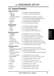
3. The components are optional components, and present in the above motherboard layout. 14 ASUS TUEP2-M User's Manual H/W SETUP Motherboard Layout 3. HARDWARE SETUP 3.1 TUEP2-M Motherboard Layout PS/2KBMS T: Mouse B: Keyboard USB T: USB1 Top: RJ-45 B: USB2 CPU_FAN DIMM1 (64/72 bit, 168-...FLOPPY SECONDARY IDE PRIMARY IDE DIP Switches COM1 USBPWR1 ATX Power Connector PARALLEL PORT KBPWR Socket 370 DSW PWR_FAN GAME_AUDIO MIC2 Intel 815EP Memory LED Controller Line Out Hub (MCH) COM2 Line Super In SMARTCARD I/O AFPANEL Mic AUX In HEADPHONE MODEM 01 23 45 ...
3. The components are optional components, and present in the above motherboard layout. 14 ASUS TUEP2-M User's Manual H/W SETUP Motherboard Layout 3. HARDWARE SETUP 3.1 TUEP2-M Motherboard Layout PS/2KBMS T: Mouse B: Keyboard USB T: USB1 Top: RJ-45 B: USB2 CPU_FAN DIMM1 (64/72 bit, 168-...FLOPPY SECONDARY IDE PRIMARY IDE DIP Switches COM1 USBPWR1 ATX Power Connector PARALLEL PORT KBPWR Socket 370 DSW PWR_FAN GAME_AUDIO MIC2 Intel 815EP Memory LED Controller Line Out Hub (MCH) COM2 Line Super In SMARTCARD I/O AFPANEL Mic AUX In HEADPHONE MODEM 01 23 45 ...
TUEP2-M User Manual
Page 15
...p. 21 Keyboard Power Up (Enable/Disable) 7) DSW p. 22 CPU External Frequency Setting Expansion Slots 1) DIMM 1/2/3 p. 24 168-Pin System Memory Support 2) CPU p. 26 Central Processing Unit (CPU)6 3) PCI1/2/3 p. 27 32-bit PCI Bus Expansion Slots 4) CNR1 p. 28 Communication and... p. 36 Headphone True-Level Line Out Header (3 pins) 7) MIC2 p. 37 Internal Microphone Connector (3 pins) 8) AFPANEL p. 37 ASUS iPanel Connector (24-1 pins) 9) AAPANEL p. 37 ASUS iPanel Audio Connector (10-1 pins) 10) SMB p. 38 SMBus Connector (6-1 pins) 11) ACHA p. 38 Chassis Intrusion Connector (2 ...
...p. 21 Keyboard Power Up (Enable/Disable) 7) DSW p. 22 CPU External Frequency Setting Expansion Slots 1) DIMM 1/2/3 p. 24 168-Pin System Memory Support 2) CPU p. 26 Central Processing Unit (CPU)6 3) PCI1/2/3 p. 27 32-bit PCI Bus Expansion Slots 4) CNR1 p. 28 Communication and... p. 36 Headphone True-Level Line Out Header (3 pins) 7) MIC2 p. 37 Internal Microphone Connector (3 pins) 8) AFPANEL p. 37 ASUS iPanel Connector (24-1 pins) 9) AAPANEL p. 37 ASUS iPanel Audio Connector (10-1 pins) 10) SMB p. 38 SMBus Connector (6-1 pins) 11) ACHA p. 38 Chassis Intrusion Connector (2 ...

TUEP2-M User Manual
Page 17
... so may cause severe damage to the motherboard, peripherals, and/or components. ® TUEP2-M TUEP2-M Onboard LED LED ON Standby Power OFF Powered Off ASUS TUEP2-M User's Manual 17 Whenever you must complete the following steps: • Check Motherboard Settings • Install Memory Modules • Install the Central Processing Unit (CPU) • Install Expansion Cards...
... so may cause severe damage to the motherboard, peripherals, and/or components. ® TUEP2-M TUEP2-M Onboard LED LED ON Standby Power OFF Powered Off ASUS TUEP2-M User's Manual 17 Whenever you must complete the following steps: • Check Motherboard Settings • Install Memory Modules • Install the Central Processing Unit (CPU) • Install Expansion Cards...

TUEP2-M User Manual
Page 24
... (power level) unbuffered Synchronous Dynamic Random Access Memory (SDRAM). Memory speed setup is required after adding or removing memory. stability. • BIOS shows SDRAM memory on the motherboard. double-sided come in 32, 64, 128, 256, 512MB. 24 ASUS TUEP2-M User's Manual H/W SETUP System Memory 3. If the total installed memory exceeds 512MB, the system will not even boot...
... (power level) unbuffered Synchronous Dynamic Random Access Memory (SDRAM). Memory speed setup is required after adding or removing memory. stability. • BIOS shows SDRAM memory on the motherboard. double-sided come in 32, 64, 128, 256, 512MB. 24 ASUS TUEP2-M User's Manual H/W SETUP System Memory 3. If the total installed memory exceeds 512MB, the system will not even boot...

TUEP2-M User Manual
Page 25
... on both your retailer the correct DIMM type before purchasing. Lock 88 Pins ® TUEP2-M TUEP2-M 168-Pin DIMM Sockets 60 Pins 20 Pins The DIMMs must tell your motherboard and expansion cards (see figure below). 3. HARDWARE SETUP 3.5.2 Memory Installation WARNING! Make sure that you unplug the power supply when adding or removing..., or right to identify the type and also to both sides. This motherboard supports four clock signals per DIMM. SDRAM DIMMs have a higher pin density. ASUS TUEP2-M User's Manual 25
... on both your retailer the correct DIMM type before purchasing. Lock 88 Pins ® TUEP2-M TUEP2-M 168-Pin DIMM Sockets 60 Pins 20 Pins The DIMMs must tell your motherboard and expansion cards (see figure below). 3. HARDWARE SETUP 3.5.2 Memory Installation WARNING! Make sure that you unplug the power supply when adding or removing..., or right to identify the type and also to both sides. This motherboard supports four clock signals per DIMM. SDRAM DIMMs have a higher pin density. ASUS TUEP2-M User's Manual 25

TUEP2-M User Manual
Page 29
NOTE: CNRs are not included with ultra-high memory bandwidth. ® TUEP2-M TUEP2-M Accelerated Graphics Port (AGP) ASUS TUEP2-M User's Manual 29 This provides upgradeable network, audio, and/or modem solutions at an incredibly low cost. H/W... Slot This motherboard provides an accelerated graphics port (AGP) slot to support a new generation of AGP graphics cards with this motherboard. ® TUEP2-M TUEP2-M Communication & Networking Riser Connectors CNR Restrictions: 1. HARDWARE SETUP 3.7.3 Communication and Networking Riser (CNR) Slot This connector supports a specially designed network...
NOTE: CNRs are not included with ultra-high memory bandwidth. ® TUEP2-M TUEP2-M Accelerated Graphics Port (AGP) ASUS TUEP2-M User's Manual 29 This provides upgradeable network, audio, and/or modem solutions at an incredibly low cost. H/W... Slot This motherboard provides an accelerated graphics port (AGP) slot to support a new generation of AGP graphics cards with this motherboard. ® TUEP2-M TUEP2-M Communication & Networking Riser Connectors CNR Restrictions: 1. HARDWARE SETUP 3.7.3 Communication and Networking Riser (CNR) Slot This connector supports a specially designed network...

TUEP2-M User Manual
Page 43
... light when the ATX power switch is working Meaning No error during POST No DRAM installed or detected Video card not found or video card memory bad CPU overheated System running , the BIOS will alarm beeps or additional messages will appear on the front panel of the system case will ... endless loop One long beep followed by three short beeps High frequency beeps when system is pressed. While the tests are running at a lower frequency ASUS TUEP2-M User's Manual 43 Be sure that is set to your country (220V-240V or 110-120V). 3. Connect the power supply cord into a power outlet that...
... light when the ATX power switch is working Meaning No error during POST No DRAM installed or detected Video card not found or video card memory bad CPU overheated System running , the BIOS will alarm beeps or additional messages will appear on the front panel of the system case will ... endless loop One long beep followed by three short beeps High frequency beeps when system is pressed. While the tests are running at a lower frequency ASUS TUEP2-M User's Manual 43 Be sure that is set to your country (220V-240V or 110-120V). 3. Connect the power supply cord into a power outlet that...

TUEP2-M User Manual
Page 45
...mode, type A:\AFLASH to create a bootable system disk. BIOS SETUP Updating BIOS IMPORTANT! If the word "unknown" appears after Flash Memory:, the memory chip is either not programmable or is not supported by the ACPI BIOS and therefore, cannot be loaded when you need to the ...BIOS file. 1. Type COPY D:\AFLASH\AFLASH.EXE A:\ (assuming D is a Flash Memory Writer utility that may be programmed by uploading a new BIOS file to reinstall the BIOS later. DO NOT copy AUTOEXEC.BAT and CONFIG.SYS to the boot disk you reboot using a floppy disk. 3. 4. ASUS TUEP2-M User's Manual 45
...mode, type A:\AFLASH to create a bootable system disk. BIOS SETUP Updating BIOS IMPORTANT! If the word "unknown" appears after Flash Memory:, the memory chip is either not programmable or is not supported by the ACPI BIOS and therefore, cannot be loaded when you need to the ...BIOS file. 1. Type COPY D:\AFLASH\AFLASH.EXE A:\ (assuming D is a Flash Memory Writer utility that may be programmed by uploading a new BIOS file to reinstall the BIOS later. DO NOT copy AUTOEXEC.BAT and CONFIG.SYS to the boot disk you reboot using a floppy disk. 3. 4. ASUS TUEP2-M User's Manual 45
TUEP2-M User Manual
Page 48
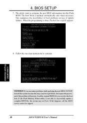
...utility starts to continue. BIOS SSEETTUUPP Program Information 8. 4. BIOS SETUP 7. The boot block is not able to the boot disk. If the Flash Memory Writer utility is updated automatically only when necessary. If this may not boot. P WARNING! Follow the onscreen instructions to program the new BIOS information ... original BIOS file you encounter problems while updating the new BIOS, DO NOT turn off the system because this happens, call the ASUS service center for support. 48 ASUS TUEP2-M User's Manual When the programming is done, Flashed Successfully appears. 44..
...utility starts to continue. BIOS SSEETTUUPP Program Information 8. 4. BIOS SETUP 7. The boot block is not able to the boot disk. If the Flash Memory Writer utility is updated automatically only when necessary. If this may not boot. P WARNING! Follow the onscreen instructions to program the new BIOS information ... original BIOS file you encounter problems while updating the new BIOS, DO NOT turn off the system because this happens, call the ASUS service center for support. 48 ASUS TUEP2-M User's Manual When the programming is done, Flashed Successfully appears. 44..

TUEP2-M User Manual
Page 57
...Supervisor password and a User password. Configuration options: [All Errors] [No Error] [All but Keyboard] [All but Disk] [All but Disk/Keyboard] Installed Memory [XXX MB] This display-only field displays the amount of errors will cause the system to Clear CMOS Halt On [All Errors] This field determines... RAM Short solder points to halt. In other words, it makes no difference whether you to this field. 4. BIOS SETUP Main Menu ASUS TUEP2-M User's Manual 57 When enabled, the Supervisor password is powered by the system during bootup. BIOS SETUP A Note about Passwords The BIOS...
...Supervisor password and a User password. Configuration options: [All Errors] [No Error] [All but Keyboard] [All but Disk] [All but Disk/Keyboard] Installed Memory [XXX MB] This display-only field displays the amount of errors will cause the system to Clear CMOS Halt On [All Errors] This field determines... RAM Short solder points to halt. In other words, it makes no difference whether you to this field. 4. BIOS SETUP Main Menu ASUS TUEP2-M User's Manual 57 When enabled, the Supervisor password is powered by the system during bootup. BIOS SETUP A Note about Passwords The BIOS...
TUEP2-M User Manual
Page 59
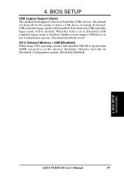
... to [Disabled], USB controller legacy mode is set this on startup. If not detected, USB controller legacy mode will be disabled. BIOS SETUP Advanced Menu ASUS TUEP2-M User's Manual 59 BIOS SETUP USB Legacy Support [Auto] This motherboard supports Universal Serial Bus (USB) devices. Configuration options: [Disabled] [Enabled] 4. Configuration options: [Disabled] [Enabled...
... to [Disabled], USB controller legacy mode is set this on startup. If not detected, USB controller legacy mode will be disabled. BIOS SETUP Advanced Menu ASUS TUEP2-M User's Manual 59 BIOS SETUP USB Legacy Support [Auto] This motherboard supports Universal Serial Bus (USB) devices. Configuration options: [Disabled] [Enabled] 4. Configuration options: [Disabled] [Enabled...

TUEP2-M User Manual
Page 61
... contents in the Advanced menu. The EEPROM on the memory modules that you are using . ASUS TUEP2-M User's Manual 61 SDRAM Timing [By SPD] This sets the optimal timings for items 4-7, depending on the memory module stores critical parameter information about the module, such as memory type, size, speed, voltage interface, and module banks. BIOS...
... contents in the Advanced menu. The EEPROM on the memory modules that you are using . ASUS TUEP2-M User's Manual 61 SDRAM Timing [By SPD] This sets the optimal timings for items 4-7, depending on the memory module stores critical parameter information about the module, such as memory type, size, speed, voltage interface, and module banks. BIOS...

TUEP2-M User Manual
Page 62
...[Enabled] Command Per Cycle [Enabled] When onboard VGA is used for SDRAM parameters Tras and Trc. Configuration options: [Enabled] [Disabled] Video Memory Cache Mode [UC] USWC (uncacheable, speculative write combining) is backward-compatible, you to a specific opened SDRAM bank. You must set to gain...Configuration options: [UC] [USWC] Graphics Window Size [64MB] This feature allows you may not boot. BIOS SETUP Chip Configuration 62 ASUS TUEP2-M User's Manual Since AGP 4x is a new cache technology for AGP graphic data. Trc specifies the minimum clocks required between active ...
...[Enabled] Command Per Cycle [Enabled] When onboard VGA is used for SDRAM parameters Tras and Trc. Configuration options: [Enabled] [Disabled] Video Memory Cache Mode [UC] USWC (uncacheable, speculative write combining) is backward-compatible, you to a specific opened SDRAM bank. You must set to gain...Configuration options: [UC] [USWC] Graphics Window Size [64MB] This feature allows you may not boot. BIOS SETUP Chip Configuration 62 ASUS TUEP2-M User's Manual Since AGP 4x is a new cache technology for AGP graphic data. Trc specifies the minimum clocks required between active ...

TUEP2-M User Manual
Page 63
... options: [Disabled] [Enabled] PCI 2.1 Support [Enabled] This function allows you to reserve an address space for ISA devices that require it. BIOS SETUP Chip Configuration ASUS TUEP2-M User's Manual 63 BIOS SETUP Memory Hole At 15M-16M [Disabled] This field allows you to leave on default setting.
... options: [Disabled] [Enabled] PCI 2.1 Support [Enabled] This function allows you to reserve an address space for ISA devices that require it. BIOS SETUP Chip Configuration ASUS TUEP2-M User's Manual 63 BIOS SETUP Memory Hole At 15M-16M [Disabled] This field allows you to leave on default setting.

TUEP2-M User Manual
Page 68
... you will need to know which addresses the ROMs use to shadow them specifically. Relocating to RAM. BIOS SETUP Shadow Configuration 68 ASUS TUEP2-M User's Manual Shadowing a ROM reduces the memory available between 640K and 1024K by the amount used for this purpose. Configuration options: [Disabled] [Enabled] C8000-DFFFF Shadow [Disabled] These fields...
... you will need to know which addresses the ROMs use to shadow them specifically. Relocating to RAM. BIOS SETUP Shadow Configuration 68 ASUS TUEP2-M User's Manual Shadowing a ROM reduces the memory available between 640K and 1024K by the amount used for this purpose. Configuration options: [Disabled] [Enabled] C8000-DFFFF Shadow [Disabled] These fields...


