User Guide
Page 3
... information 1-8 1.7.1 Front panel LEDs 1-8 1.7.2 Rear panel LEDs 1-9 Chapter 2: Hardware setup 2.1 Chassis cover 2-2 2.1.1 Removing the side cover 2-2 2.1.2 Reinstalling the side cover 2-3 2.2 Central Processing Unit (CPU 2-4 2.2.1 Installing the CPU 2-4 2.2.2 Installing the CPU heatsink and fan 2-7 2.3 System memory 2-8 2.3.1 Overview 2-8 2.3.2 Memory Configurations 2-9 2.3.3 Installing a DIMM 2-10 2.3.4 Removing a DIMM 2-10 2.4 Front panel assembly 2-11 2.4.1 Removing the front panel assembly...
... information 1-8 1.7.1 Front panel LEDs 1-8 1.7.2 Rear panel LEDs 1-9 Chapter 2: Hardware setup 2.1 Chassis cover 2-2 2.1.1 Removing the side cover 2-2 2.1.2 Reinstalling the side cover 2-3 2.2 Central Processing Unit (CPU 2-4 2.2.1 Installing the CPU 2-4 2.2.2 Installing the CPU heatsink and fan 2-7 2.3 System memory 2-8 2.3.1 Overview 2-8 2.3.2 Memory Configurations 2-9 2.3.3 Installing a DIMM 2-10 2.3.4 Removing a DIMM 2-10 2.4 Front panel assembly 2-11 2.4.1 Removing the front panel assembly...
User Guide
Page 5
...-up window 5-7 5.2.8 Scroll bar 5-7 5.2.9 General help 5-7 5.3 Main menu 5-8 5.3.1 System Time 5-8 5.3.2 System Date 5-8 5.3.3 SATA1-6 5-8 5.3.4 IDE Configuration 5-10 5.3.5 AHCI Configuration 5-11 5.3.6 System Information 5-12 5.4 Advanced menu 5-13 5.4.1 CPU Configuration 5-13 5.4.2 Chipset Configuration 5-17 5.4.3 Legacy Device Configuration 5-21 5.4.4 USB Configuration 5-22 5.4.5 PCIPnP Configuration 5-23 5.4.6 Power On configuration 5-24 5.4.7 Event Log Configuration 5-25 5.4.8 Hardware Monitor...
...-up window 5-7 5.2.8 Scroll bar 5-7 5.2.9 General help 5-7 5.3 Main menu 5-8 5.3.1 System Time 5-8 5.3.2 System Date 5-8 5.3.3 SATA1-6 5-8 5.3.4 IDE Configuration 5-10 5.3.5 AHCI Configuration 5-11 5.3.6 System Information 5-12 5.4 Advanced menu 5-13 5.4.1 CPU Configuration 5-13 5.4.2 Chipset Configuration 5-17 5.4.3 Legacy Device Configuration 5-21 5.4.4 USB Configuration 5-22 5.4.5 PCIPnP Configuration 5-23 5.4.6 Power On configuration 5-24 5.4.7 Event Log Configuration 5-25 5.4.8 Hardware Monitor...
User Guide
Page 12
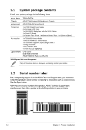
.... TS500-E6/PS4 xxxxxxxxxxxx 1-2 Chapter 1: Product introduction With the correct serial number of the product's serial number containing 12 characters such as xxxxxxxxxxxx. Rear: 1 x 120mm x 38mm) Accessories 1 x TS500-E6 User's Guide 1 x ASUS ASWM 2.0 User's Guide 1 x TS500-E6 Support CD (including ASWM*) 1 x Bag of Screws 1 x AC Power Cable 1 x Anti-virus CD (Optional) Optional Items CPU Cooler DVD-ROM / DVD-RW ASUS TS500-E6...
.... TS500-E6/PS4 xxxxxxxxxxxx 1-2 Chapter 1: Product introduction With the correct serial number of the product's serial number containing 12 characters such as xxxxxxxxxxxx. Rear: 1 x 120mm x 38mm) Accessories 1 x TS500-E6 User's Guide 1 x ASUS ASWM 2.0 User's Guide 1 x TS500-E6 Support CD (including ASWM*) 1 x Bag of Screws 1 x AC Power Cable 1 x Anti-virus CD (Optional) Optional Items CPU Cooler DVD-ROM / DVD-RW ASUS TS500-E6...
User Guide
Page 13
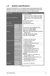
... 3.5" HDD Bays swappable (continued on the next page) ASUS TS500-E6/PS4 1-3 Supports RAID 0,1,5,10 & 6 ASUS PIKE 6480 SAS RAID card - Supports RAID 0,1,5 & 10 I /O controller ASUS Features Smart Fan ASWM2.0 √ √ Total Slots 6 (3-channel per CPU, 3 DIMMs per CPU) Capacity Maximum up to 48GB (RDIMM) Maximum up to...card - Quad-Core Intel® Xeon® E5500 Series (80W) - 1.3 System specifications The ASUS TS500-E6/PS4 is a 5U barebone server system featuring the ASUS Z8NA-D6 server board. The server supports Intel® LGA1366 Xeon® 5500 series processors, ...
... 3.5" HDD Bays swappable (continued on the next page) ASUS TS500-E6/PS4 1-3 Supports RAID 0,1,5,10 & 6 ASUS PIKE 6480 SAS RAID card - Supports RAID 0,1,5 & 10 I /O controller ASUS Features Smart Fan ASWM2.0 √ √ Total Slots 6 (3-channel per CPU, 3 DIMMs per CPU) Capacity Maximum up to 48GB (RDIMM) Maximum up to...card - Quad-Core Intel® Xeon® E5500 Series (80W) - 1.3 System specifications The ASUS TS500-E6/PS4 is a 5U barebone server system featuring the ASUS Z8NA-D6 server board. The server supports Intel® LGA1366 Xeon® 5500 series processors, ...
User Guide
Page 14
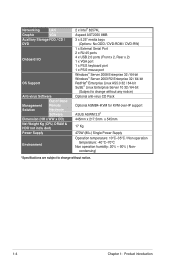
... / CD / DVD Onboard I/O OS Support Anti-virus Software Out of Band Management Solution Remote Hardware Software Dimension (HH x WW x DD) Net Weight Kg (CPU, DRAM & HDD not inclu ded) Power Supply Environment 2 x Intel® 82574L Aspeed AST2050 8MB 3 x 5.25" media bays (Options: No ODD / ...Product introduction condensing) *Specifications are subject to change without any notice) Optional anti-virus CD Pack Optional ASMB4-iKVM for KVM-over-IP support ASUS ASWM 2.0® 445mm x 217.5mm x 545mm 17 Kg 470W (80+) Single Power Supply Operation temperature: 10°C-35°C / Non...
... / CD / DVD Onboard I/O OS Support Anti-virus Software Out of Band Management Solution Remote Hardware Software Dimension (HH x WW x DD) Net Weight Kg (CPU, DRAM & HDD not inclu ded) Power Supply Environment 2 x Intel® 82574L Aspeed AST2050 8MB 3 x 5.25" media bays (Options: No ODD / ...Product introduction condensing) *Specifications are subject to change without any notice) Optional anti-virus CD Pack Optional ASMB4-iKVM for KVM-over-IP support ASUS ASWM 2.0® 445mm x 217.5mm x 545mm 17 Kg 470W (80+) Single Power Supply Operation temperature: 10°C-35°C / Non...
User Guide
Page 22
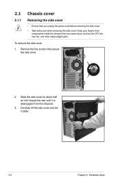
Carefully lift the side cover and set it is disengaged from components inside the chassis that can cause injury, such as the CPU fan, rear fan, and other sharp-edged parts. Remove the two screws that you unplug the power cord before removing the side cover. • Take ...
Carefully lift the side cover and set it is disengaged from components inside the chassis that can cause injury, such as the CPU fan, rear fan, and other sharp-edged parts. Remove the two screws that you unplug the power cord before removing the side cover. • Take ...
User Guide
Page 24
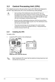
...contacts resulting from incorrect CPU installation/removal, or misplacement/loss/ incorrect removal of the motherboard, ensure that the PnP cap is on the Socket 1366. • The product warranty does not cover damage to the PnP cap/socket contacts/motherboard components. ASUS will process Return ...Merchandise Authorization (RMA) requests only if the motherboard comes with dual surface mount LGA 1366 Socket designed for the Intel® Xeon 5500 series CPU in the Land Grid Array (LGA) package. ...
...contacts resulting from incorrect CPU installation/removal, or misplacement/loss/ incorrect removal of the motherboard, ensure that the PnP cap is on the Socket 1366. • The product warranty does not cover damage to the PnP cap/socket contacts/motherboard components. ASUS will process Return ...Merchandise Authorization (RMA) requests only if the motherboard comes with dual surface mount LGA 1366 Socket designed for the Intel® Xeon 5500 series CPU in the Land Grid Array (LGA) package. ...
User Guide
Page 25
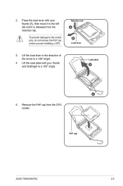
Load plate 4 3 5. Lift the load lever in the direction of the arrow to the socket pins, do not remove the PnP cap unless you are installing a CPU. PnP cap ASUS TS500-E6/PS4 2-5 2. To prevent damage to a 135º angle. 4. Remove the PnP cap from the retention tab. Retention tab A B Load lever 3. Lift the load plate with your thumb and forefinger to the left (B) until it to a 100º angle. Press the load lever with your thumb (A), then move it is released from the CPU socket.
Load plate 4 3 5. Lift the load lever in the direction of the arrow to the socket pins, do not remove the PnP cap unless you are installing a CPU. PnP cap ASUS TS500-E6/PS4 2-5 2. To prevent damage to a 135º angle. 4. Remove the PnP cap from the retention tab. Retention tab A B Load lever 3. Lift the load plate with your thumb and forefinger to the left (B) until it to a 100º angle. Press the load lever with your thumb (A), then move it is released from the CPU socket.
User Guide
Page 26
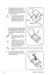
... Gold triangle mark 7. Apply several drops of thermal paste to the exposed area of the socket, and then fit the socket alignment key into the CPU notch. If it is spread in an even thin layer. Close the load plate (A), and then push the load lever (B) until it off immediately...with, ensuring that the gold triangle is toxic and inedible. If so, skip this step. The thermal paste is on the socket and damaging the CPU! To prevent contaminating the paste, DO NOT spread the paste with preapplied thermal paste. Some heatsinks come with your skin, ensure to prevent bending the...
... Gold triangle mark 7. Apply several drops of thermal paste to the exposed area of the socket, and then fit the socket alignment key into the CPU notch. If it is spread in an even thin layer. Close the load plate (A), and then push the load lever (B) until it off immediately...with, ensuring that the gold triangle is toxic and inedible. If so, skip this step. The thermal paste is on the socket and damaging the CPU! To prevent contaminating the paste, DO NOT spread the paste with preapplied thermal paste. Some heatsinks come with your skin, ensure to prevent bending the...
User Guide
Page 27
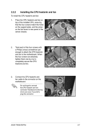
...match the holes on the support plate, and the arrow on the motherboard. Twist each of the server chassis. 2. Connect the CPU heatsink and fan cable to the connector on the fan faces to rear panel of the four screws with a Philips (cross) ...CPU heatsink and fan. 3. Hardware monitoring errors can occur if you fail to connect the CPU heatsink and fan connector! Do not forget to plug this connector. 2.2.2 Installing the CPU heatsink and fan To install the CPU heatsink and fan: 1. When the four screws are attached, tighten them one by one to the motherboard. ASUS TS500-E6/PS4...
...match the holes on the support plate, and the arrow on the motherboard. Twist each of the server chassis. 2. Connect the CPU heatsink and fan cable to the connector on the fan faces to rear panel of the four screws with a Philips (cross) ...CPU heatsink and fan. 3. Hardware monitoring errors can occur if you fail to connect the CPU heatsink and fan connector! Do not forget to plug this connector. 2.2.2 Installing the CPU heatsink and fan To install the CPU heatsink and fan: 1. When the four screws are attached, tighten them one by one to the motherboard. ASUS TS500-E6/PS4...
User Guide
Page 29
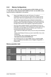
... from the same vendor. For effective use of the lower-sized channel for the OS can be about 3GB or less. ASUS TS500-E6/PS4 2-9 The system maps the total size of memory, we recommend that you want to the memory address limitation on 32-bit... Megabit, 8 Megabit/Mb = 1 Megabyte/MB). DIMM_E1 -- DIMM_C1 --- Refer to the Microsoft® support site at http://support.microsoft.com/kb/929605/en-us. • This motherboard does not support DIMMs made up of the following: - Memory population table CPU 1 Configuration DIMM_A1 1 DIMMs 2 DIMMs 3 DIMMs CPU 2 Configuration DIMM_D1 1...
... from the same vendor. For effective use of the lower-sized channel for the OS can be about 3GB or less. ASUS TS500-E6/PS4 2-9 The system maps the total size of memory, we recommend that you want to the memory address limitation on 32-bit... Megabit, 8 Megabit/Mb = 1 Megabyte/MB). DIMM_E1 -- DIMM_C1 --- Refer to the Microsoft® support site at http://support.microsoft.com/kb/929605/en-us. • This motherboard does not support DIMMs made up of the following: - Memory population table CPU 1 Configuration DIMM_A1 1 DIMMs 2 DIMMs 3 DIMMs CPU 2 Configuration DIMM_D1 1...
User Guide
Page 55
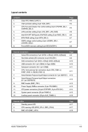
...) 12. Standby power LED 2. Clear RTC RAM (CLRTC1) 2. VGA controller setting (3-pin VGA_SW1) 3. iBTN RAID setting (3-pin IBTN_SEL1) 7. DDR3 voltage control setting (4-pin LVDDR3_SEL1, LVDDR3_SEL2) 8. A-Type USB5) 5. CPU, front and rear fan connectors (4-pin CPU_FAN1-2,... Serial General Purpose Input/Output connector (6-1 pin SGPIO1) 8. System panel connector (20-pin PANEL1) 13. CPU warning LED (ERR_CPU1, ERR_CPU2) 3. BMC LED (BMC_LED1) Page 4-17 4-17 4-18 ASUS TS500-E6/PS4 4-3 Intel ICH10R® SATA ports S/W RAID setting (3-pin RAID_SEL1) 6. Force BIOS recovery setting (3-pin ...
...) 12. Standby power LED 2. Clear RTC RAM (CLRTC1) 2. VGA controller setting (3-pin VGA_SW1) 3. iBTN RAID setting (3-pin IBTN_SEL1) 7. DDR3 voltage control setting (4-pin LVDDR3_SEL1, LVDDR3_SEL2) 8. A-Type USB5) 5. CPU, front and rear fan connectors (4-pin CPU_FAN1-2,... Serial General Purpose Input/Output connector (6-1 pin SGPIO1) 8. System panel connector (20-pin PANEL1) 13. CPU warning LED (ERR_CPU1, ERR_CPU2) 3. BMC LED (BMC_LED1) Page 4-17 4-17 4-18 ASUS TS500-E6/PS4 4-3 Intel ICH10R® SATA ports S/W RAID setting (3-pin RAID_SEL1) 6. Force BIOS recovery setting (3-pin ...
User Guide
Page 57
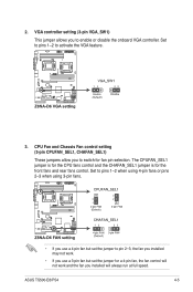
CPU Fan and Chassis Fan control setting (3-pin CPUFAN_SEL1, CHAFAN_SEL1) These jumpers allow you to switch for fan pin selection. VGA controller setting (3-pin VGA_SW1) This ... fans or pins 2-3 when using 3-pin fans. • If you use a 4-pin fan but set the jumper to activate the VGA feature. 3. ASUS TS500-E6/PS4 4-5 2. The CPUFAN_SEL1 jumper is for the CPU fans control and the CHAFAN_SEL1 jumper is for a 4-pin fan, the fan control will not work and the fan you installed will...
CPU Fan and Chassis Fan control setting (3-pin CPUFAN_SEL1, CHAFAN_SEL1) These jumpers allow you to switch for fan pin selection. VGA controller setting (3-pin VGA_SW1) This ... fans or pins 2-3 when using 3-pin fans. • If you use a 4-pin fan but set the jumper to activate the VGA feature. 3. ASUS TS500-E6/PS4 4-5 2. The CPUFAN_SEL1 jumper is for the CPU fans control and the CHAFAN_SEL1 jumper is for a 4-pin fan, the fan control will not work and the fan you installed will...
User Guide
Page 63
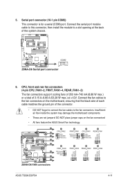
ASUS TS500-E6/PS4 4-11 Insufficient air flow inside the system may damage the motherboard components. • These are not jumpers! CPU, front and rear fan connectors (4-pin CPU_FAN1-2, FRNT_FAN1-4, REAR_FAN1-2) The fan connectors support cooling fans of 350 mA-740 mA (8.88 W max.) or a ... connector is for a serial (COM) port. Connect the fan cables to the fan connectors on the fan connectors! • All fans feature the ASUS Smart Fan technology. 5. Connect the serial port module cable to this connector, then install the module to the fan connectors. DO NOT place jumper caps...
ASUS TS500-E6/PS4 4-11 Insufficient air flow inside the system may damage the motherboard components. • These are not jumpers! CPU, front and rear fan connectors (4-pin CPU_FAN1-2, FRNT_FAN1-4, REAR_FAN1-2) The fan connectors support cooling fans of 350 mA-740 mA (8.88 W max.) or a ... connector is for a serial (COM) port. Connect the fan cables to the fan connectors on the fan connectors! • All fans feature the ASUS Smart Fan technology. 5. Connect the serial port module cable to this connector, then install the module to the fan connectors. DO NOT place jumper caps...
User Guide
Page 69
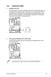
The illustration below shows the location of the corresponding CPU. The green LED lights up to indicate that the system is a reminder that an impending failure of the onboard LED. 2. ASUS TS500-E6/PS4 4-17 This is ON, in sleep mode, or in any motherboard component. 4.4 Internal LEDs 1. The warning LEDs function only when you should...
The illustration below shows the location of the corresponding CPU. The green LED lights up to indicate that the system is a reminder that an impending failure of the onboard LED. 2. ASUS TS500-E6/PS4 4-17 This is ON, in sleep mode, or in any motherboard component. 4.4 Internal LEDs 1. The warning LEDs function only when you should...
User Guide
Page 77
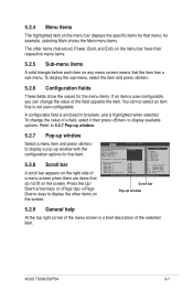
... side of a menu screen when there are items that is not user-configurable. To change the value of the field opposite the item. ASUS TS500-E6/PS4 5-7 Advanced BIOS SETUP UTILITY CPU Bridge Chipset Configuration USB Functions [1D2isUaSbBlePdorts] USB Port Configure [82X4USUBSBPoProtrsts] USB 2.0 Controller [E4naUbSlBedP]orts HDA Controller [E6naUbSlBedP]orts SMBUS Controller [E8naUbSlBedP]orts 10...
... side of a menu screen when there are items that is not user-configurable. To change the value of the field opposite the item. ASUS TS500-E6/PS4 5-7 Advanced BIOS SETUP UTILITY CPU Bridge Chipset Configuration USB Functions [1D2isUaSbBlePdorts] USB Port Configure [82X4USUBSBPoProtrsts] USB 2.0 Controller [E4naUbSlBedP]orts HDA Controller [E6naUbSlBedP]orts SMBUS Controller [E8naUbSlBedP]orts 10...
User Guide
Page 82
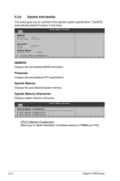
... Memory Configuration CPU2 Memory Configuration BIOS SETUP UTILITY CPU1/2 Memory Configuration Allows you an overview of installed memory (3 DIMMs per CPU). 5-12 Chapter 5: BIOS setup System Memory Information Displays system memory information. 5.3.6 System Information This menu gives you to ... information of the general system specifications. The BIOS automatically detects the items in this menu. Processor Displays the auto-detected CPU specification. Main BIOS SETUP UTILITY AMIBIOS Version :0204 Build Date :02/16/09 Processor Speed Count :2400MHZ :1 System ...
... Memory Configuration CPU2 Memory Configuration BIOS SETUP UTILITY CPU1/2 Memory Configuration Allows you an overview of installed memory (3 DIMMs per CPU). 5-12 Chapter 5: BIOS setup System Memory Information Displays system memory information. 5.3.6 System Information This menu gives you to ... information of the general system specifications. The BIOS automatically detects the items in this menu. Processor Displays the auto-detected CPU specification. Main BIOS SETUP UTILITY AMIBIOS Version :0204 Build Date :02/16/09 Processor Speed Count :2400MHZ :1 System ...
User Guide
Page 83
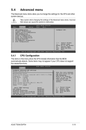
ASUS TS500-E6/PS4 5-13 5.4 Advanced menu The Advanced menu items allow you to malfunction. Advanced BIOS SETUP UTILITY Configure advanced CPU settings Module Version:3F.11 Manufacturer:Intel Brand String:Genuine Intel(R) CPU @ 0000 @ 2.67GHz Frequency :2.66GHz BCLK Speed :133MHz Cache L1 :128...v02.61 (C)Copyright 1985-2009, American Megatrends, Inc. Main Advanced Server BIOS SETUP UTILITY Boot Exit CPU Configuration Chipset Configuration Legacy Device Configuration USB Configuration PCIPnP Configuration Power On Configuration Event Log Configuration Hardware Monitor ...
ASUS TS500-E6/PS4 5-13 5.4 Advanced menu The Advanced menu items allow you to malfunction. Advanced BIOS SETUP UTILITY Configure advanced CPU settings Module Version:3F.11 Manufacturer:Intel Brand String:Genuine Intel(R) CPU @ 0000 @ 2.67GHz Frequency :2.66GHz BCLK Speed :133MHz Cache L1 :128...v02.61 (C)Copyright 1985-2009, American Megatrends, Inc. Main Advanced Server BIOS SETUP UTILITY Boot Exit CPU Configuration Chipset Configuration Legacy Device Configuration USB Configuration PCIPnP Configuration Power On Configuration Event Log Configuration Hardware Monitor ...
User Guide
Page 84
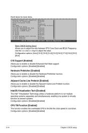
... Demotion [Enabled] C3 Auto Demotion [Enabled] v02.61 (C)Copyright 1985-2009, American Megatrends, Inc. Ratio CMOS Setting [Auto] Allows you to adjust the ratio between CPU Core Clock and BCLK Frequency. Configuration options: [Auto] [12.0] [13.0] [14.0] [15.0] [16.0] [17.0] [18.0] [19.0] [20.0] C1E Support ... multiple operating systems separately and simultaneously, enabling one system to virtually function as several systems. Configuration options: [Disabled] [Enabled] CPU TM Function [Enabled] This function enables the overheated CPU to throttle the clock speed to adjust the value.
... Demotion [Enabled] C3 Auto Demotion [Enabled] v02.61 (C)Copyright 1985-2009, American Megatrends, Inc. Ratio CMOS Setting [Auto] Allows you to adjust the ratio between CPU Core Clock and BCLK Frequency. Configuration options: [Auto] [12.0] [13.0] [14.0] [15.0] [16.0] [17.0] [18.0] [19.0] [20.0] C1E Support ... multiple operating systems separately and simultaneously, enabling one system to virtually function as several systems. Configuration options: [Disabled] [Enabled] CPU TM Function [Enabled] This function enables the overheated CPU to throttle the clock speed to adjust the value.
User Guide
Page 85
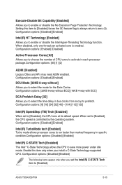
...to run faster than marked frequency in specific condition.Configuration options: [Disabled] [Enabled] Intel(R) C-STATE Tech [Enabled] The Intel® C-State Technology allows the CPU to enable or disable the Intel Hyper-Threading Technology function. Configuration options: [Disabled] [Enabled] Intel(R) HT Technology [Enabled] Allows you to save more power under... options: [Disabled] [Enabled] DCU Mode [32KB 8-way without ECC] [16KB 4-way with ECC] DCA Prefetch Delay [32] Allows you to choose the number of CPU cores to select the mode for the Data Cache. ASUS TS500-E6/PS4 5-15
...to run faster than marked frequency in specific condition.Configuration options: [Disabled] [Enabled] Intel(R) C-STATE Tech [Enabled] The Intel® C-State Technology allows the CPU to enable or disable the Intel Hyper-Threading Technology function. Configuration options: [Disabled] [Enabled] Intel(R) HT Technology [Enabled] Allows you to save more power under... options: [Disabled] [Enabled] DCU Mode [32KB 8-way without ECC] [16KB 4-way with ECC] DCA Prefetch Delay [32] Allows you to choose the number of CPU cores to select the mode for the Data Cache. ASUS TS500-E6/PS4 5-15


