
User Guide
Page 4
.../SAS hard disk drives 2-16 2.6.1 Hot-swap HDD module 2-16 2.7 Expansion cards 2-20 2.7.1 Installing an expansion card 2-20 2.7.2 Installing ASUS PIKE RAID card 2-21 2.7.3 Configuring an expansion card 2-22 2.8 Cable connections 2-23 2.8.1 Motherboard connections 2-23 2.8.2 SATA/SAS backplane connections 2-24 2.9 Removable components 2-26 2.9.1 System fan 2-26 2.9.2 Chassis footpads 2-28 2.9.3 Power supply unit...
.../SAS hard disk drives 2-16 2.6.1 Hot-swap HDD module 2-16 2.7 Expansion cards 2-20 2.7.1 Installing an expansion card 2-20 2.7.2 Installing ASUS PIKE RAID card 2-21 2.7.3 Configuring an expansion card 2-22 2.8 Cable connections 2-23 2.8.1 Motherboard connections 2-23 2.8.2 SATA/SAS backplane connections 2-24 2.9 Removable components 2-26 2.9.1 System fan 2-26 2.9.2 Chassis footpads 2-28 2.9.3 Power supply unit...

User Guide
Page 9
... change system settings through the BIOS Setup menus and describes the BIOS parameters. 6. Chapter 4: Motherboard information This chapter gives information about the motherboard that you have to install optional components into the barebone server. 4. This chapter includes the motherboard layout, jumper settings, and connector locations. 5. ix Chapter 1: Product Introduction This chapter describes the...
... change system settings through the BIOS Setup menus and describes the BIOS parameters. 6. Chapter 4: Motherboard information This chapter gives information about the motherboard that you have to install optional components into the barebone server. 4. This chapter includes the motherboard layout, jumper settings, and connector locations. 5. ix Chapter 1: Product Introduction This chapter describes the...
User Guide
Page 12
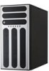
... below. 1.1 System package contents Check your system package for the following items. Model Name Chassis Motherboard Component Accessories Optional Items TS500-E5/PA4 TS500-E5/RX8 ASUS T55 Pedestal 5U Rackmount ASUS T55 Pedestal 5U Rackmount Chassis Chassis ASUS DSAN-DX/TS500-E5 Server ASUS DSAN-DX/TS500-E5 Server Board Board 1 x 670W Single Power Supply 1 x 650W Redundant Power Supply 1 x SATA/SAS Backplane (BP4LX...
... below. 1.1 System package contents Check your system package for the following items. Model Name Chassis Motherboard Component Accessories Optional Items TS500-E5/PA4 TS500-E5/RX8 ASUS T55 Pedestal 5U Rackmount ASUS T55 Pedestal 5U Rackmount Chassis Chassis ASUS DSAN-DX/TS500-E5 Server ASUS DSAN-DX/TS500-E5 Server Board Board 1 x 670W Single Power Supply 1 x 650W Redundant Power Supply 1 x SATA/SAS Backplane (BP4LX...

User Guide
Page 17
1.5 Rear panel features The rear panel includes a slot for the motherboard rear I/O ports, expansion slots, a chassis lock and intrusion switch, a vent for the system fan, and power supply module. 1.5.1 Single power supply (PA4 model) PS/2 mouse port PS/2 keyboard port USB 2.0 ports Serial port VGA port Gigabit LAN port 1 Gigabit LAN port 2 670W... x 38mm system fan Expansion slots 1.5.2 Redundant Power Supply (RX8 model) Power connector 650W Redundant power supply The second redundant power supply is an optional item. ASUS TS500-E5 1-7
1.5 Rear panel features The rear panel includes a slot for the motherboard rear I/O ports, expansion slots, a chassis lock and intrusion switch, a vent for the system fan, and power supply module. 1.5.1 Single power supply (PA4 model) PS/2 mouse port PS/2 keyboard port USB 2.0 ports Serial port VGA port Gigabit LAN port 1 Gigabit LAN port 2 670W... x 38mm system fan Expansion slots 1.5.2 Redundant Power Supply (RX8 model) Power connector 650W Redundant power supply The second redundant power supply is an optional item. ASUS TS500-E5 1-7
User Guide
Page 24
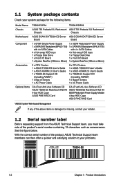
... your left. 2-4 Chapter 2: Hardware setup ASUS will light up if a single CPU is installed on the socket and the socket contacts are not bent. CPU1 CPU2 DSAN-DX ® DSAN-DX/TS500-E5 CPU LGA771 Before installing the CPU, make sure that the socket box is on the motherboard. Contact your retailer immediately if...
... your left. 2-4 Chapter 2: Hardware setup ASUS will light up if a single CPU is installed on the socket and the socket contacts are not bent. CPU1 CPU2 DSAN-DX ® DSAN-DX/TS500-E5 CPU LGA771 Before installing the CPU, make sure that the socket box is on the motherboard. Contact your retailer immediately if...
User Guide
Page 27
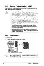
... them one by one to the connector on the support plate. 2. ASUS TS500-E5 2-7 Place the CPU heatsink and fan on top of the four screws with a Philips (cross) screwdriver just enough to attach the CPU heatsink and fan to the motherboard. Do not forget to plug this connector. Hardware monitoring errors can occur... to connect the CPU heatsink and fan connector! Twist each of the installed CPU, making sure that the four screws match the holes on the motherboard. 2.2.2 Installing the CPU heatsink and fan To install the CPU heatsink and fan: 1.
... them one by one to the connector on the support plate. 2. ASUS TS500-E5 2-7 Place the CPU heatsink and fan on top of the four screws with a Philips (cross) screwdriver just enough to attach the CPU heatsink and fan to the motherboard. Do not forget to plug this connector. Hardware monitoring errors can occur... to connect the CPU heatsink and fan connector! Twist each of the installed CPU, making sure that the four screws match the holes on the motherboard. 2.2.2 Installing the CPU heatsink and fan To install the CPU heatsink and fan: 1.
User Guide
Page 28
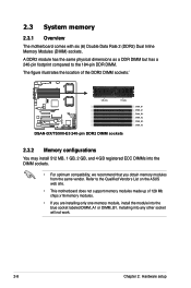
...-pin footprint compared to the Qualified Vendors List on the ASUS web site. • This motherboard does not support memory modules made up of the DDR2 DIMM sockets:` DSAN-DX ® 128 pins 112 pins DSAN-DX/TS500-E5 240-pin DDR2 DIMM sockets DIMM_B1 DIMM_A1 DIMM_B2 DIMM_A2 DIMM_B3 ...any other socket will not work. 2-8 Chapter 2: Hardware setup Installing into the blue socket labeled DIMM_A1 or DIMM_B1. 2.3 System memory 2.3.1 Overview The motherboard comes with six (6) Double Data Rate 2 (DDR2) Dual Inline Memory Modules (DIMM) sockets. Refer to the 184-pin DDR DIMM. The ...
...-pin footprint compared to the Qualified Vendors List on the ASUS web site. • This motherboard does not support memory modules made up of the DDR2 DIMM sockets:` DSAN-DX ® 128 pins 112 pins DSAN-DX/TS500-E5 240-pin DDR2 DIMM sockets DIMM_B1 DIMM_A1 DIMM_B2 DIMM_A2 DIMM_B3 ...any other socket will not work. 2-8 Chapter 2: Hardware setup Installing into the blue socket labeled DIMM_A1 or DIMM_B1. 2.3 System memory 2.3.1 Overview The motherboard comes with six (6) Double Data Rate 2 (DDR2) Dual Inline Memory Modules (DIMM) sockets. Refer to the 184-pin DDR DIMM. The ...
User Guide
Page 30
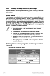
... the "spared" DIMM rank will be assigned as spare rank. Refer to a larger sized one. • A DIMM can be enabled or disabled separately. • This motherboard does not support rank sparing across channels. • The DIMM rank with Memory Sparing function in its own sparing engine and can contain only one...
... the "spared" DIMM rank will be assigned as spare rank. Refer to a larger sized one. • A DIMM can be enabled or disabled separately. • This motherboard does not support rank sparing across channels. • The DIMM rank with Memory Sparing function in its own sparing engine and can contain only one...
User Guide
Page 32
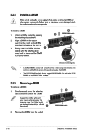
... DIMM notch 1 Unlocked retaining clip • A DDR2 DIMM is keyed with your fingers when pressing the retaining clips. 2.3.4 Installing a DIMM Make sure to both the motherboard and the components. Align a DIMM on the socket such that it flips out with extra force. 1 2. Remove the DIMM from the socket. 2 1 DDR2 DIMM notch...
... DIMM notch 1 Unlocked retaining clip • A DDR2 DIMM is keyed with your fingers when pressing the retaining clips. 2.3.4 Installing a DIMM Make sure to both the motherboard and the components. Align a DIMM on the socket such that it flips out with extra force. 1 2. Remove the DIMM from the socket. 2 1 DDR2 DIMM notch...
User Guide
Page 34
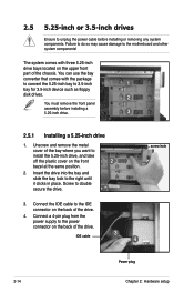
... 2 bezel at the same position. 2. Connect the IDE cable to the right until it clicks in place. 2.5 5.25-inch or 3.5-inch drives Ensure to the motherboard and other system components! Failure to do so may cause damage to unplug the power cable before installing a 5.25-inch drive. 3 2.5.1 Installing a 5.25-inch drive...
... 2 bezel at the same position. 2. Connect the IDE cable to the right until it clicks in place. 2.5 5.25-inch or 3.5-inch drives Ensure to the motherboard and other system components! Failure to do so may cause damage to unplug the power cable before installing a 5.25-inch drive. 3 2.5.1 Installing a 5.25-inch drive...
User Guide
Page 41
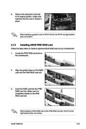
... RAID card slot. Locate the PIKE RAID card slot on your motherboard. 1. Align the golden fingers of the RAID card with the PIKE RAID card slot. 3. ASUS TS500-E5 2-21 Restore the expansion card lock to install an optional ASUS RAID card on the motherboard. 2. When installing a graphics card on PCI-E x16 slot, the PCI-E... light click indicates that the card is completely seated on the PIKE RAID card slot, the PCI-E slot right beside it does not function. 2.7.2 Installing ASUS PIKE RAID card Follow the steps below to its original position. Make sure it is locked in place. 6.
... RAID card slot. Locate the PIKE RAID card slot on your motherboard. 1. Align the golden fingers of the RAID card with the PIKE RAID card slot. 3. ASUS TS500-E5 2-21 Restore the expansion card lock to install an optional ASUS RAID card on the motherboard. 2. When installing a graphics card on PCI-E x16 slot, the PCI-E... light click indicates that the card is completely seated on the PIKE RAID card slot, the PCI-E slot right beside it does not function. 2.7.2 Installing ASUS PIKE RAID card Follow the steps below to its original position. Make sure it is locked in place. 6.
User Guide
Page 43
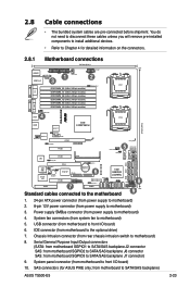
... SATA/SAS backplane J7 connector) 9. IDE connector (from power supply to Chapter 4 for ASUS PIKE only; Power supply SMBus connector (from motherboard to motherboard) 4. System panel connector (from power supply to front I /O board) 6. from motherboard to SATA/SAS backplane) ASUS TS500-E5 2-23 You do not need to disconnect these cables unless you will remove pre‑...
... SATA/SAS backplane J7 connector) 9. IDE connector (from power supply to Chapter 4 for ASUS PIKE only; Power supply SMBus connector (from motherboard to motherboard) 4. System panel connector (from power supply to front I /O board) 6. from motherboard to SATA/SAS backplane) ASUS TS500-E5 2-23 You do not need to disconnect these cables unless you will remove pre‑...
User Guide
Page 45
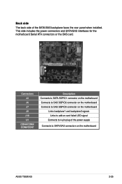
... U1 CON4/CON5/ CON6/CON7 Description Connects to SATA SGPIO1 connector on the motherboard Connects to SAS SGPIO2 connector on the motherboard Connects to SAS SGPIO3 connector on the motherboard Links backplane1 and backplane2 signals Links to add-on the motherboard ASUS TS500-E5 2-25 This side includes the power connectors and SATA/SAS interfaces for the...
... U1 CON4/CON5/ CON6/CON7 Description Connects to SATA SGPIO1 connector on the motherboard Connects to SAS SGPIO2 connector on the motherboard Connects to SAS SGPIO3 connector on the motherboard Links backplane1 and backplane2 signals Links to add-on the motherboard ASUS TS500-E5 2-25 This side includes the power connectors and SATA/SAS interfaces for the...
User Guide
Page 46
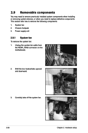
System fan 2. Shift the two hooked tabs upward and downward. 3. Chassis footpads 3. 2.9 Removable components You may need to remove previously installed system components when installing or removing system devices, or when you need to remove the following components: 1. Unplug the system fan cable from the REAR_FAN2 connector on the motherboard. 2. Carefully take off the system fan. 2-26 Chapter 2: Hardware setup Power supply unit 2.9.1 System fan To remove the system fan: 1. This section tells how to replace defective components.
System fan 2. Shift the two hooked tabs upward and downward. 3. Chassis footpads 3. 2.9 Removable components You may need to remove previously installed system components when installing or removing system devices, or when you need to remove the following components: 1. Unplug the system fan cable from the REAR_FAN2 connector on the motherboard. 2. Carefully take off the system fan. 2-26 Chapter 2: Hardware setup Power supply unit 2.9.1 System fan To remove the system fan: 1. This section tells how to replace defective components.
User Guide
Page 47
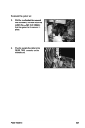
Shift the two hooked tabs upward and downward, and then install the system fan. A light click indicates that the system fan is secured in place. 2. To reinstall the system fan: 1. Plug the system fan cable to the REAR_FAN2 connector on the motherboard. ASUS TS500-E5 2-27
Shift the two hooked tabs upward and downward, and then install the system fan. A light click indicates that the system fan is secured in place. 2. To reinstall the system fan: 1. Plug the system fan cable to the REAR_FAN2 connector on the motherboard. ASUS TS500-E5 2-27
User Guide
Page 49
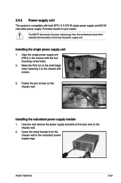
... PSU sit on your needs. ASUS TS500-E5 2-29 Installing the redundant power supply module 1. You MUST disconnect all power cable plugs from the chassis wall to the chassis with both EPS 12 V 670 W single power supply and 650 W redundant power supply. Screw the metal bracket from the motherboard and other installed devices before...
... PSU sit on your needs. ASUS TS500-E5 2-29 Installing the redundant power supply module 1. You MUST disconnect all power cable plugs from the chassis wall to the chassis with both EPS 12 V 670 W single power supply and 650 W redundant power supply. Screw the metal bracket from the motherboard and other installed devices before...
User Guide
Page 55
Motherboard info Chapter 4 This chapter includes the motherboard layout, and brief descriptions of the jumpers and internal connectors.
Motherboard info Chapter 4 This chapter includes the motherboard layout, and brief descriptions of the jumpers and internal connectors.
User Guide
Page 56
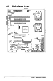
4.1 Motherboard layout KBMS1 USB12_L3 PSUSMB 24.5cm (9.6in) EATXPWR1 CPU_FAN1 EATX12V1 COM1 DDR DIMM_B1 (64bit, 240-pin module) DDR DIMM_A1..., 240-pin module) DDR DIMM_B3 (64bit, 240-pin module) DDR DIMM_A3 (64bit, 240-pin module) CPUFAN_SEL1 VGA1 CPU1 DSAN-DX/TS500-E5 ® LAN1 REAR_FAN2 LAN2 BCM5721 LAN_SW1 BCM5721 REAR_FAN1 COM2 PCIE1 LAN_SW2 PCIE2 Intel 5100P MCH PCIE3 Z9s VGA_SW1 PCI4 AMI 8Mb RECOVERY1 IDE_SW1... SATA4 Intel 82801IR (ICH9R) SATA5 SATA6 FRNT_FAN1 HDLED SGPIO3 SGPIO2 SGPIO1 PANEL1 24.5cm (9.6in) FLOPPY1 4-2 Chapter 4: Motherboard information
4.1 Motherboard layout KBMS1 USB12_L3 PSUSMB 24.5cm (9.6in) EATXPWR1 CPU_FAN1 EATX12V1 COM1 DDR DIMM_B1 (64bit, 240-pin module) DDR DIMM_A1..., 240-pin module) DDR DIMM_B3 (64bit, 240-pin module) DDR DIMM_A3 (64bit, 240-pin module) CPUFAN_SEL1 VGA1 CPU1 DSAN-DX/TS500-E5 ® LAN1 REAR_FAN2 LAN2 BCM5721 LAN_SW1 BCM5721 REAR_FAN1 COM2 PCIE1 LAN_SW2 PCIE2 Intel 5100P MCH PCIE3 Z9s VGA_SW1 PCI4 AMI 8Mb RECOVERY1 IDE_SW1... SATA4 Intel 82801IR (ICH9R) SATA5 SATA6 FRNT_FAN1 HDLED SGPIO3 SGPIO2 SGPIO1 PANEL1 24.5cm (9.6in) FLOPPY1 4-2 Chapter 4: Motherboard information
User Guide
Page 58
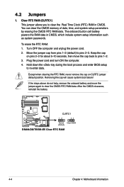
... CMOS memory of date, time, and system setup parameters by erasing the CMOS RTC RAM data. DSAN-DX/TS500-E5 ® CLRTC1 12 23 Normal Clear CMOS (Default) DSAN-DX/TS500-E5 Clear RTC RAM 4-4 Chapter 4: Motherboard information Move the jumper cap from pins 1-2 (default) to re-enter data. If the steps above do not...
... CMOS memory of date, time, and system setup parameters by erasing the CMOS RTC RAM data. DSAN-DX/TS500-E5 ® CLRTC1 12 23 Normal Clear CMOS (Default) DSAN-DX/TS500-E5 Clear RTC RAM 4-4 Chapter 4: Motherboard information Move the jumper cap from pins 1-2 (default) to re-enter data. If the steps above do not...
User Guide
Page 60
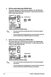
Set to pins 1-2 when using 4-pin fans or pins 2-3 when using 3-pin fans. DSAN-DX/TS500-E5 ® CHAFAN_SEL1 12 23 4-Pin FAN 3-Pin FAN (Default) DSAN-DX/TS500-E5 CHAFAN setting • If you use a 3-pin fan but set the jumper to switch for a 4-pin fan, the fan controll ... fan you installed will always run at full speed. 4-6 Chapter 4: Motherboard information 4. The CPUFAN_SEL1 jumper is for the CPU fans control. CPUFAN_SEL1 12 23 4-Pin FAN 3-Pin FAN (Default) DSAN-DX/TS500-E5 ® DSAN-DX/TS500-E5 CPUFAN setting • If you use a 3-pin fan but set ...
Set to pins 1-2 when using 4-pin fans or pins 2-3 when using 3-pin fans. DSAN-DX/TS500-E5 ® CHAFAN_SEL1 12 23 4-Pin FAN 3-Pin FAN (Default) DSAN-DX/TS500-E5 CHAFAN setting • If you use a 3-pin fan but set the jumper to switch for a 4-pin fan, the fan controll ... fan you installed will always run at full speed. 4-6 Chapter 4: Motherboard information 4. The CPUFAN_SEL1 jumper is for the CPU fans control. CPUFAN_SEL1 12 23 4-Pin FAN 3-Pin FAN (Default) DSAN-DX/TS500-E5 ® DSAN-DX/TS500-E5 CPUFAN setting • If you use a 3-pin fan but set ...

