User Guide
Page 13
Product introduction Chapter 1 This chapter describes the general features of the server, including sections on front panel and rear panel specifications. ASUS TS300-E8-PS4
Product introduction Chapter 1 This chapter describes the general features of the server, including sections on front panel and rear panel specifications. ASUS TS300-E8-PS4
User Guide
Page 15
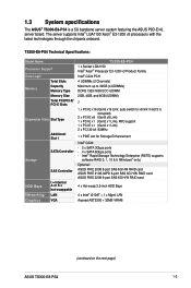
... Family Intel® C224 PCH 4 UDIMMs (2 Channels) Maximum up to x8 link if slot 5 is a 5U barebone server system featuring the ASUS P9D-E/4L server board. 1.3 System specifications The ASUS® TS300-E8-PS4 is occupied) 2 x PCI-E x8 (Gen3 x8 Link) 1 x PCI-E x1 (Gen2 x1 Link), MIO support 1 x PCI-E x1... RAID card 4 x Hot-swap 3.5-inch HDD Bays 4 x Intel® I210AT + 1 x Mgmt LAN Aspeed AST2300 + 32MB VRAM (continued on the next page) ASUS TS300-E8-PS4 1-3 auto-switch to 32GB (4 UDIMMs) DDR3 1333/1600 ECC UDIMM 2GB, 4GB, and 8GB (UDIMM) 7 1 x PCI-E x16 (Gen3 x16 Link; The server ...
... Family Intel® C224 PCH 4 UDIMMs (2 Channels) Maximum up to x8 link if slot 5 is a 5U barebone server system featuring the ASUS P9D-E/4L server board. 1.3 System specifications The ASUS® TS300-E8-PS4 is occupied) 2 x PCI-E x8 (Gen3 x8 Link) 1 x PCI-E x1 (Gen2 x1 Link), MIO support 1 x PCI-E x1... RAID card 4 x Hot-swap 3.5-inch HDD Bays 4 x Intel® I210AT + 1 x Mgmt LAN Aspeed AST2300 + 32MB VRAM (continued on the next page) ASUS TS300-E8-PS4 1-3 auto-switch to 32GB (4 UDIMMs) DDR3 1333/1600 ECC UDIMM 2GB, 4GB, and 8GB (UDIMM) 7 1 x PCI-E x16 (Gen3 x16 Link; The server ...
User Guide
Page 17
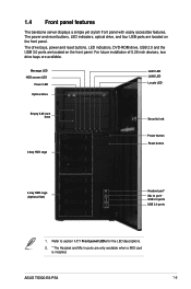
...-inch bays 4-bay HDD cage Security lock Power button Reset button 4-bay HDD cage (Optional Set) Headset port* Mic In port* USB 2.0 ports USB 3.0 ports 1. ASUS TS300-E8-PS4 1-5 Refer to section 1.7.1 Front panel LEDs for the LED descriptions. 2. * The Headset and Mic In ports are available. 1.4 Front panel features The barebone server displays...
...-inch bays 4-bay HDD cage Security lock Power button Reset button 4-bay HDD cage (Optional Set) Headset port* Mic In port* USB 2.0 ports USB 3.0 ports 1. ASUS TS300-E8-PS4 1-5 Refer to section 1.7.1 Front panel LEDs for the LED descriptions. 2. * The Headset and Mic In ports are available. 1.4 Front panel features The barebone server displays...
User Guide
Page 19
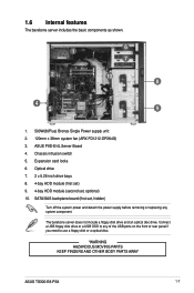
... panel if you need to use a floppy disk or a optical disc. *WARNING HAZARDOUS MOVING PARTS KEEP FINGERS AND OTHER BODY PARTS AWAY ASUS TS300-E8-PS4 1-7 Connect a USB floppy disk drive or a USB ODD to any system component. Expansion card locks 6. SATA/SAS backplane board (first... set , optional) 10. The barebone server does not include a floppy disk drive and an optical disc drive. ASUS P9D-E/4L Server Board 4. 1.6 Internal features The barebone server includes the basic components as shown. 1 2 3 4 5 6 7 10 8 9 1. 500W(80Plus...
... panel if you need to use a floppy disk or a optical disc. *WARNING HAZARDOUS MOVING PARTS KEEP FINGERS AND OTHER BODY PARTS AWAY ASUS TS300-E8-PS4 1-7 Connect a USB floppy disk drive or a USB ODD to any system component. Expansion card locks 6. SATA/SAS backplane board (first... set , optional) 10. The barebone server does not include a floppy disk drive and an optical disc drive. ASUS P9D-E/4L Server Board 4. 1.6 Internal features The barebone server includes the basic components as shown. 1 2 3 4 5 6 7 10 8 9 1. 500W(80Plus...
User Guide
Page 21
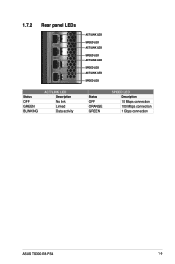
1.7.2 Rear panel LEDs Status OFF GREEN BLINKING ACT/LINK LED Description No link Linked Data activity ACT/LINK LED SPEED LED ACT/LINK LED SPEED LED ACT/LINK LED SPEED LED ACT/LINK LED SPEED LED Status OFF ORANGE GREEN SPEED LED Description 10 Mbps connection 100 Mbps connection 1 Gbps connection ASUS TS300-E8-PS4 1-9
1.7.2 Rear panel LEDs Status OFF GREEN BLINKING ACT/LINK LED Description No link Linked Data activity ACT/LINK LED SPEED LED ACT/LINK LED SPEED LED ACT/LINK LED SPEED LED ACT/LINK LED SPEED LED Status OFF ORANGE GREEN SPEED LED Description 10 Mbps connection 100 Mbps connection 1 Gbps connection ASUS TS300-E8-PS4 1-9
User Guide
Page 23
Hardware setup Chapter 2 This chapter lists the hardware setup procedures that you have to perform when installing or removing system components. ASUS TS300-E8-PS4
Hardware setup Chapter 2 This chapter lists the hardware setup procedures that you have to perform when installing or removing system components. ASUS TS300-E8-PS4
User Guide
Page 25
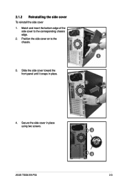
Match and insert the bottom edge of the side cover to the chassis. 3. Slide the side cover toward the front panel until it snaps in place using two screws. ASUS TS300-E8-PS4 4 4 2-3 Position the side cover on to the corresponding chassis edge. 2. Secure the side cover in place. 1 3 4. 2.1.2 Reinstalling the side cover To reinstall the side cover 1.
Match and insert the bottom edge of the side cover to the chassis. 3. Slide the side cover toward the front panel until it snaps in place using two screws. ASUS TS300-E8-PS4 4 4 2-3 Position the side cover on to the corresponding chassis edge. 2. Secure the side cover in place. 1 3 4. 2.1.2 Reinstalling the side cover To reinstall the side cover 1.
User Guide
Page 27
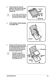
... force the CPU into the socket to the right (B) until the load plate is completely lifted. Gold triangle mark Alignment key CPU notches Alignment key ASUS TS300-E8-PS4 2-5 Load lever Retention tab Load plate 4. Lift the load lever until it to prevent bending the pins on the bottom-left corner of the socket...
... force the CPU into the socket to the right (B) until the load plate is completely lifted. Gold triangle mark Alignment key CPU notches Alignment key ASUS TS300-E8-PS4 2-5 Load lever Retention tab Load plate 4. Lift the load lever until it to prevent bending the pins on the bottom-left corner of the socket...
User Guide
Page 29
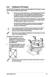
... to install while the special heatsink assembly requires a Phillips screwdriver to the CPU heatsink or CPU before you install the CPU fan and heatsink assembly. ASUS TS300-E8-PS4 2-7 The LGA1150 socket is incompatible with a CPU fan assembly is properly applied to tighten or loosen screws. • Use an LGA1150-compatible CPU heatsink and...
... to install while the special heatsink assembly requires a Phillips screwdriver to the CPU heatsink or CPU before you install the CPU fan and heatsink assembly. ASUS TS300-E8-PS4 2-7 The LGA1150 socket is incompatible with a CPU fan assembly is properly applied to tighten or loosen screws. • Use an LGA1150-compatible CPU heatsink and...
User Guide
Page 31
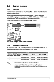
... Speed 1333/1600 1333/1600 Rank per DIMM Single Rank, Dual Rank Single Rank, Dual Rank • Begin installing the DIMMs from the same vendor. ASUS TS300-E8-PS4 2-9 The figure illustrates the location of the DDR3 DIMM sockets: 2.3.2 Memory Configurations You may install 2 GB, 4 GB, and 8 GB Unbuffered with the same CAS latency...
... Speed 1333/1600 1333/1600 Rank per DIMM Single Rank, Dual Rank Single Rank, Dual Rank • Begin installing the DIMMs from the same vendor. ASUS TS300-E8-PS4 2-9 The figure illustrates the location of the DDR3 DIMM sockets: 2.3.2 Memory Configurations You may install 2 GB, 4 GB, and 8 GB Unbuffered with the same CAS latency...
User Guide
Page 33
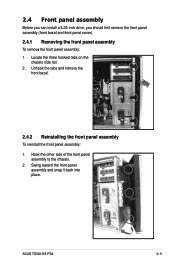
Swing toward the front panel assembly and snap it back into place. 2.4 Front panel assembly Before you can install a 5.25-inch drive, you should first remove the front panel assembly (front bezel and front panel cover). 2.4.1 Removing the front panel assembly To remove the front panel assembly: 1. ASUS TS300-E8-PS4 2-11 Unhook the tabs and remove the front bezel. 2.4.2 Reinstalling the front panel assembly To reinstall the front panel assembly: 1. Hook the other side of the front panel assembly to the chassis. 2. Locate the three hooked tabs on the chassis side rail. 2.
Swing toward the front panel assembly and snap it back into place. 2.4 Front panel assembly Before you can install a 5.25-inch drive, you should first remove the front panel assembly (front bezel and front panel cover). 2.4.1 Removing the front panel assembly To remove the front panel assembly: 1. ASUS TS300-E8-PS4 2-11 Unhook the tabs and remove the front bezel. 2.4.2 Reinstalling the front panel assembly To reinstall the front panel assembly: 1. Hook the other side of the front panel assembly to the chassis. 2. Locate the three hooked tabs on the chassis side rail. 2.
User Guide
Page 35
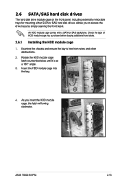
..., including externally removable trays for mounting either SATA or SAS hard disk drives, allows you insert the HDD module cage, the latch will swing clockwise. ASUS TS300-E8-PS4 2-13 An HDD module cage comes with a SATA or SAS backplane. Insert the HDD module cage into the bay. 3 2 4. Examine the chassis and ensure the...
..., including externally removable trays for mounting either SATA or SAS hard disk drives, allows you insert the HDD module cage, the latch will swing clockwise. ASUS TS300-E8-PS4 2-13 An HDD module cage comes with a SATA or SAS backplane. Insert the HDD module cage into the bay. 3 2 4. Examine the chassis and ensure the...
User Guide
Page 37
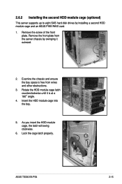
.... 6. Insert the HDD module cage into 4 the bay. 3 5. Examine the chassis and ensure the bay space is at a 1800 angle. 4. Lock the cage latch properly. 6 ASUS TS300-E8-PS4 2-15 2.6.2 Installing the second HDD module cage (optional) This server supports up to eight SAS hard disk drives by swinging it is free from the...
.... 6. Insert the HDD module cage into 4 the bay. 3 5. Examine the chassis and ensure the bay space is at a 1800 angle. 4. Lock the cage latch properly. 6 ASUS TS300-E8-PS4 2-15 2.6.2 Installing the second HDD module cage (optional) This server supports up to eight SAS hard disk drives by swinging it is free from the...
User Guide
Page 39
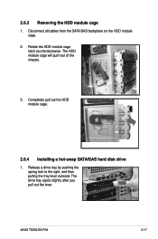
Disconnect all cables from the SATA/SAS backplane on the HDD module cage. 2. The HDD module cage will push out of the chassis. 3. ASUS TS300-E8-PS4 2-17 Rotate the HDD module cage latch counterclockwise. Completely pull out the HDD module cage. 2.6.4 Installing a hot-swap SATA/SAS hard disk drive 1. Release a drive tray by pushing the spring lock to the right, and then pulling the tray lever outward. The drive tray ejects slightly after you pull out the lever. 2.6.3 Removing the HDD module cage 1.
Disconnect all cables from the SATA/SAS backplane on the HDD module cage. 2. The HDD module cage will push out of the chassis. 3. ASUS TS300-E8-PS4 2-17 Rotate the HDD module cage latch counterclockwise. Completely pull out the HDD module cage. 2.6.4 Installing a hot-swap SATA/SAS hard disk drive 1. Release a drive tray by pushing the spring lock to the right, and then pulling the tray lever outward. The drive tray ejects slightly after you pull out the lever. 2.6.3 Removing the HDD module cage 1.
User Guide
Page 41
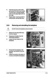
... placed when its front edge aligns with the bay edge. 7. Disconnect all hot-swap HDD trays from the chassis. 2. Follow the previous instructions in place. ASUS TS300-E8-PS4 2-19 6. Repeat steps 1 to 6 if you wish to reinstall the backplane. Firmly hold the backplane, lift it from the SATA/SAS backplane. 3. Remove all cables...
... placed when its front edge aligns with the bay edge. 7. Disconnect all hot-swap HDD trays from the chassis. 2. Follow the previous instructions in place. ASUS TS300-E8-PS4 2-19 6. Repeat steps 1 to 6 if you wish to reinstall the backplane. Firmly hold the backplane, lift it from the SATA/SAS backplane. 3. Remove all cables...
User Guide
Page 43
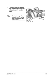
Restore the expansion card lock to its original position. ASUS TS300-E8-PS4 2-21 A light click indicates the card is locked in A place. B When installing a graphics card on a PCI-E x16 slot, the PCI-E slot right beside it will not be available. 7.
Restore the expansion card lock to its original position. ASUS TS300-E8-PS4 2-21 A light click indicates the card is locked in A place. B When installing a graphics card on a PCI-E x16 slot, the PCI-E slot right beside it will not be available. 7.
User Guide
Page 45
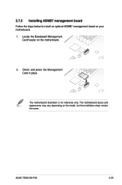
The motherboard illustration is for reference only. The motherboard layout and appearance may vary depending on your motherboard. 1. ASUS TS300-E8-PS4 2-23 2.7.3 Installing ASMB7 management board Follow the steps below to install an optional ASMB7 management board on the model, but the installation steps remain the same. Locate the Baseboard Management Card header on the motherboard. 2. Orient and press the Management Card in place.
The motherboard illustration is for reference only. The motherboard layout and appearance may vary depending on your motherboard. 1. ASUS TS300-E8-PS4 2-23 2.7.3 Installing ASMB7 management board Follow the steps below to install an optional ASMB7 management board on the model, but the installation steps remain the same. Locate the Baseboard Management Card header on the motherboard. 2. Orient and press the Management Card in place.
User Guide
Page 47
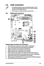
...) 5. USB 3.0 connector (from motherboard to front I/O board) 6. SAS connectors (for detailed information on the connectors. SATA conectors (system default; Serial General Purpose Input/Output connectors ASUS TS300-E8-PS4 2-25 USB 2.0 connector (from motherboard to motherboard) 8. 2.8 2.8.1 Cable connections • The bundled system cables are pre-connected before shipment. Motherboard connections 2 1 3 6 5 ... to install additional devices. • Refer to motherboard) 3. Chassis Intrusion connector (from power supply to Chapter 4 for ASUS PIKE only;
...) 5. USB 3.0 connector (from motherboard to front I/O board) 6. SAS connectors (for detailed information on the connectors. SATA conectors (system default; Serial General Purpose Input/Output connectors ASUS TS300-E8-PS4 2-25 USB 2.0 connector (from motherboard to motherboard) 8. 2.8 2.8.1 Cable connections • The bundled system cables are pre-connected before shipment. Motherboard connections 2 1 3 6 5 ... to install additional devices. • Refer to motherboard) 3. Chassis Intrusion connector (from power supply to Chapter 4 for ASUS PIKE only;
User Guide
Page 49
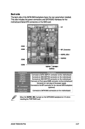
This side includes the power connectors and SATA/SAS interfaces for the motherboard Serial ATA connectors or the SAS card. ASUS TS300-E8-PS4 2-27 U1 CON1 CON2 CON4 BP_Connector BP_Connector SGPIO_SEL1 SGPIO2 CON3 Connectors SGPIO1 SGPIO2 SGPIO3 BPSMB1 U1 BP_Connector CON1/CON2/ CON3/CON4 SGPIO1 BPSMB1 SGPIO3 Description ...
This side includes the power connectors and SATA/SAS interfaces for the motherboard Serial ATA connectors or the SAS card. ASUS TS300-E8-PS4 2-27 U1 CON1 CON2 CON4 BP_Connector BP_Connector SGPIO_SEL1 SGPIO2 CON3 Connectors SGPIO1 SGPIO2 SGPIO3 BPSMB1 U1 BP_Connector CON1/CON2/ CON3/CON4 SGPIO1 BPSMB1 SGPIO3 Description ...
User Guide
Page 51
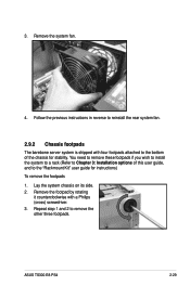
...) To remove the footpads 1. Repeat step 1 and 2 to reinstall the rear system fan. 2.9.2 Chassis footpads The barebone server system is shipped with a Philips (cross) screwdriver. 3. ASUS TS300-E8-PS4 2-29 You need to remove these footpads if you wish to install the system to a rack (Refer to the "Rackmount Kit" user guide for stability...
...) To remove the footpads 1. Repeat step 1 and 2 to reinstall the rear system fan. 2.9.2 Chassis footpads The barebone server system is shipped with a Philips (cross) screwdriver. 3. ASUS TS300-E8-PS4 2-29 You need to remove these footpads if you wish to install the system to a rack (Refer to the "Rackmount Kit" user guide for stability...


