User Guide
Page 1
TS300-E8-PS4 Pedestal/5U Rackmount Servers User Guide
TS300-E8-PS4 Pedestal/5U Rackmount Servers User Guide
User Guide
Page 4
...17 2.6.5 Removing and reinstalling the backplane 2-19 2.7 Expansion cards 2-20 2.7.1 Installing an expansion card 2-20 2.7.2 Installing ASUS PIKE RAID card 2-22 2.7.3 Installing ASMB7 management board 2-23 2.7.4 Configuring an expansion card 2-24 2.8 Cable connections ...29 Chapter 3: Installation options 3.1 Preparing the system for rack mounting 3-2 3.2 Attaching the inner rail to the server 3-2 3.3 Attaching the rails to the rack 3-3 3.4 Mounting the server to the rack 3-4 Chapter 4: Motherboard Info 4.1 Motherboard overview 4-2 4.1.1 Placement direction 4-2 4.1.2 Screw holes 4-2...
...17 2.6.5 Removing and reinstalling the backplane 2-19 2.7 Expansion cards 2-20 2.7.1 Installing an expansion card 2-20 2.7.2 Installing ASUS PIKE RAID card 2-22 2.7.3 Installing ASMB7 management board 2-23 2.7.4 Configuring an expansion card 2-24 2.8 Cable connections ...29 Chapter 3: Installation options 3.1 Preparing the system for rack mounting 3-2 3.2 Attaching the inner rail to the server 3-2 3.3 Attaching the rails to the rack 3-3 3.4 Mounting the server to the rack 3-4 Chapter 4: Motherboard Info 4.1 Motherboard overview 4-2 4.1.1 Placement direction 4-2 4.1.2 Screw holes 4-2...
User Guide
Page 6
Contents 5.4.10 NCT6779D Super IO Configuration 5-22 5.4.11 Intel Server Platform Services 5-23 5.4.12 Onboard LAN Configuration 5-24 5.4.13 MIO Card Configuration 5-24 5.4.14 Serial Port Console Redirection 5-25 5.4.15 Runtime Error Logging Support 5-27 5.4....
Contents 5.4.10 NCT6779D Super IO Configuration 5-22 5.4.11 Intel Server Platform Services 5-23 5.4.12 Onboard LAN Configuration 5-24 5.4.13 MIO Card Configuration 5-24 5.4.14 Serial Port Console Redirection 5-25 5.4.15 Runtime Error Logging Support 5-27 5.4....
User Guide
Page 9
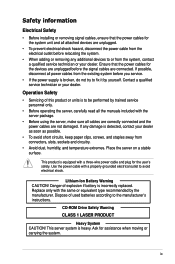
... system unit and all the manuals included with the same or equivalent type recommended by trained service personnel only. • Before operating the server, carefully read all attached devices are not damaged. If possible, disconnect all cables are correctly connected and the power cables are unplugged. &#... is heavy. Use the power cable with a three-wire power cable and plug for assistance when moving or carrying the system. Place the server on a stable surface. Lithium-Ion Battery Warning CAUTION! Danger of this product or units is broken, do not try to the manufacturer's ...
... system unit and all the manuals included with the same or equivalent type recommended by trained service personnel only. • Before operating the server, carefully read all attached devices are not damaged. If possible, disconnect all cables are correctly connected and the power cables are unplugged. &#... is heavy. Use the power cable with a three-wire power cable and plug for assistance when moving or carrying the system. Place the server on a stable surface. Lithium-Ion Battery Warning CAUTION! Danger of this product or units is broken, do not try to the manufacturer's ...
User Guide
Page 11
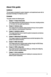
...Hardware setup This chapter lists the hardware setup procedures that you have to install the optional components and devices into the barebone server. 4. Chapter 6: RAID configuration This chapter provides instructions for setting up, creating and configuring RAID sets using the available ...This chapter provides instructions for installing the necessary drivers for system integrators, and experienced users with at least basic knowledge of the server, including sections on front panel and rear panel specifications. 2. Chapter 3: Installation options This chapter describes how to perform when...
...Hardware setup This chapter lists the hardware setup procedures that you have to install the optional components and devices into the barebone server. 4. Chapter 6: RAID configuration This chapter provides instructions for setting up, creating and configuring RAID sets using the available ...This chapter provides instructions for installing the necessary drivers for system integrators, and experienced users with at least basic knowledge of the server, including sections on front panel and rear panel specifications. 2. Chapter 3: Installation options This chapter describes how to perform when...

User Guide
Page 12
...to the components when trying to set up and use the proprietary ASUS server management utility. 2. Example: means that you must press the Enter or Return key. ++ If you complete a task. ASUS Server Web-based Management (ASWM) user guide This manual tells how to...throughout this manual. Example: At the DOS prompt, type the command line: format A:/S References Refer to the ASUS contact information. ASUS websites The ASUS websites worldwide provide updated information for product and software updates. 1. Keys enclosed in brackets. Typography Bold text ...
...to the components when trying to set up and use the proprietary ASUS server management utility. 2. Example: means that you must press the Enter or Return key. ++ If you complete a task. ASUS Server Web-based Management (ASWM) user guide This manual tells how to...throughout this manual. Example: At the DOS prompt, type the command line: format A:/S References Refer to the ASUS contact information. ASUS websites The ASUS websites worldwide provide updated information for product and software updates. 1. Keys enclosed in brackets. Typography Bold text ...
User Guide
Page 13
Product introduction Chapter 1 This chapter describes the general features of the server, including sections on front panel and rear panel specifications. ASUS TS300-E8-PS4
Product introduction Chapter 1 This chapter describes the general features of the server, including sections on front panel and rear panel specifications. ASUS TS300-E8-PS4
User Guide
Page 14
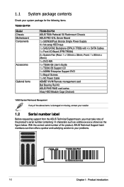
... of the above items is damaged or missing, contact your problems. TS300-E8-PS4 xxS0xxxxxxxxxx 1-2 Chapter 1: Product introduction 1.1 System package contents Check your system package for the following items. TS300-E8-PS4 Model Chassis Motherboard Components Accessories Optional Items TS300-E8-PS4 ASUS T50A Pedestal 5U Rackmount Chassis ASUS P9D-E/4L Server Board 1 x 500W(80Plus) Bronze Single Power Supply 4 x hot-swap HDD...
... of the above items is damaged or missing, contact your problems. TS300-E8-PS4 xxS0xxxxxxxxxx 1-2 Chapter 1: Product introduction 1.1 System package contents Check your system package for the following items. TS300-E8-PS4 Model Chassis Motherboard Components Accessories Optional Items TS300-E8-PS4 ASUS T50A Pedestal 5U Rackmount Chassis ASUS P9D-E/4L Server Board 1 x 500W(80Plus) Bronze Single Power Supply 4 x hot-swap HDD...
User Guide
Page 15
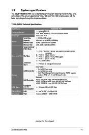
...-1200 v3 Product Family Intel® C224 PCH 4 UDIMMs (2 Channels) Maximum up to x8 link if slot 5 is a 5U barebone server system featuring the ASUS P9D-E/4L server board. 1.3 System specifications The ASUS® TS300-E8-PS4 is occupied) 2 x PCI-E x8 (Gen3 x8 Link) 1 x PCI-E x1 (Gen2 x1 Link), MIO support 1 x PCI-E x1 (Gen2 x1 Link) 2 x PCI...
...-1200 v3 Product Family Intel® C224 PCH 4 UDIMMs (2 Channels) Maximum up to x8 link if slot 5 is a 5U barebone server system featuring the ASUS P9D-E/4L server board. 1.3 System specifications The ASUS® TS300-E8-PS4 is occupied) 2 x PCI-E x8 (Gen3 x8 Link) 1 x PCI-E x1 (Gen2 x1 Link), MIO support 1 x PCI-E x1 (Gen2 x1 Link) 2 x PCI...
User Guide
Page 17
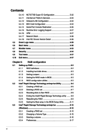
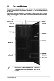
For future installation of 5.25-inch devices, two drive bays are located on the front panel. ASUS TS300-E8-PS4 1-5 The power and reset buttons, LED indicators, optical drive, and four USB ports are available. Message LED HDD access LED Power LED Optical drive LAN1 ... reset buttons, LED indicators, DVD-ROM drive, USB 2.0 and the USB 3.0 ports are only available when a MIO card is installed. 1.4 Front panel features The barebone server displays a simple yet stylish front panel with easily accessible features.
For future installation of 5.25-inch devices, two drive bays are located on the front panel. ASUS TS300-E8-PS4 1-5 The power and reset buttons, LED indicators, optical drive, and four USB ports are available. Message LED HDD access LED Power LED Optical drive LAN1 ... reset buttons, LED indicators, DVD-ROM drive, USB 2.0 and the USB 3.0 ports are only available when a MIO card is installed. 1.4 Front panel features The barebone server displays a simple yet stylish front panel with easily accessible features.
User Guide
Page 19
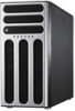
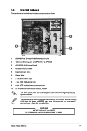
...need to use a floppy disk or a optical disc. *WARNING HAZARDOUS MOVING PARTS KEEP FINGERS AND OTHER BODY PARTS AWAY ASUS TS300-E8-PS4 1-7 The barebone server does not include a floppy disk drive and an optical disc drive. Connect a USB floppy disk drive or a USB ODD... to any system component. ASUS P9D-E/4L Server Board 4. SATA/SAS backplane board (first set , optional) 10. Expansion card locks 6. 1.6 Internal features The barebone server includes the basic components as shown. 1 2 3 4 5 6 7 10 8 9 1. 500W(...
...need to use a floppy disk or a optical disc. *WARNING HAZARDOUS MOVING PARTS KEEP FINGERS AND OTHER BODY PARTS AWAY ASUS TS300-E8-PS4 1-7 The barebone server does not include a floppy disk drive and an optical disc drive. Connect a USB floppy disk drive or a USB ODD... to any system component. ASUS P9D-E/4L Server Board 4. SATA/SAS backplane board (first set , optional) 10. Expansion card locks 6. 1.6 Internal features The barebone server includes the basic components as shown. 1 2 3 4 5 6 7 10 8 9 1. 500W(...
User Guide
Page 20
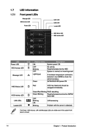
... System power ON OFF Blinking OFF No activity Read/write data into the SATAII/ SAS HDD OFF Blinking ON LAN accessing Blinking Problem with the server is detected. Green/Red Blinking RAID rebuilding Green Blinking Read/write data from/into the HDD System is normal; no incoming event Lighting up A hardware...
... System power ON OFF Blinking OFF No activity Read/write data into the SATAII/ SAS HDD OFF Blinking ON LAN accessing Blinking Problem with the server is detected. Green/Red Blinking RAID rebuilding Green Blinking Read/write data from/into the HDD System is normal; no incoming event Lighting up A hardware...

User Guide
Page 24
... the two screws that can cause injury, such as the CPU fan, rear fan, and other sharp-edged parts. • The images of the barebone server shown in this section are for reference purposes only and may not exactly match the model you purchase. Slide the side cover about half an...
... the two screws that can cause injury, such as the CPU fan, rear fan, and other sharp-edged parts. • The images of the barebone server shown in this section are for reference purposes only and may not exactly match the model you purchase. Slide the side cover about half an...
User Guide
Page 37
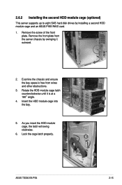
... Rotate the HDD module cage latch counterclockwise until it outward. 2. Lock the cage latch properly. 6 ASUS TS300-E8-PS4 2-15 Remove the front plate from the server chassis by installing a second HDD module cage and an ASUS PIKE RAID card. 1. As you insert the HDD module cage, the latch will swing clockwise. ...6. 2.6.2 Installing the second HDD module cage (optional) This server supports up to eight ...
... Rotate the HDD module cage latch counterclockwise until it outward. 2. Lock the cage latch properly. 6 ASUS TS300-E8-PS4 2-15 Remove the front plate from the server chassis by installing a second HDD module cage and an ASUS PIKE RAID card. 1. As you insert the HDD module cage, the latch will swing clockwise. ...6. 2.6.2 Installing the second HDD module cage (optional) This server supports up to eight ...
User Guide
Page 51
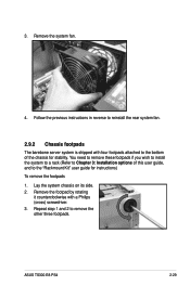
... rotating it counterclockwise with four footpads attached to the bottom of this user guide, and to reinstall the rear system fan. 2.9.2 Chassis footpads The barebone server system is shipped with a Philips (cross) screwdriver. 3. Follow the previous instructions in reverse to the "Rackmount Kit" user guide for stability. Repeat step 1 and 2 to... on its side. 2. You need to remove these footpads if you wish to install the system to a rack (Refer to remove the other three footpads. ASUS TS300-E8-PS4 2-29 3.
... rotating it counterclockwise with four footpads attached to the bottom of this user guide, and to reinstall the rear system fan. 2.9.2 Chassis footpads The barebone server system is shipped with a Philips (cross) screwdriver. 3. Follow the previous instructions in reverse to the "Rackmount Kit" user guide for stability. Repeat step 1 and 2 to... on its side. 2. You need to remove these footpads if you wish to install the system to a rack (Refer to remove the other three footpads. ASUS TS300-E8-PS4 2-29 3.

User Guide
Page 53
Installation options Chapter 3 This chapter describes how to install the optional components and devices into the barebone server. ASUS TS300-E8-PS4
Installation options Chapter 3 This chapter describes how to install the optional components and devices into the barebone server. ASUS TS300-E8-PS4

User Guide
Page 54
... footpads for the optional configurations described in this chapter are purchased separately. • We recommend that you allot at least 1U space above the server system to the server 1. 3.1 Preparing the system for rack mounting • The items required for instructions on removing the footpads. Slide out the inner rail from the...
... footpads for the optional configurations described in this chapter are purchased separately. • We recommend that you allot at least 1U space above the server system to the server 1. 3.1 Preparing the system for rack mounting • The items required for instructions on removing the footpads. Slide out the inner rail from the...
User Guide
Page 55
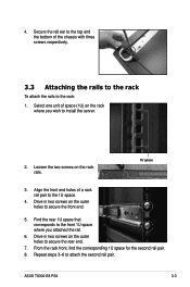
.... 1U space 3. Select one unit of the chassis with three screws respectively. 3.3 Attaching the rails to the rack To attach the rails to install the server. 2. ASUS TS300-E8-PS4 3-3 From the rack front, find the corresponding 1U space for the second rail pair. 8. Loosen the two screws on the rack where you attached the...
.... 1U space 3. Select one unit of the chassis with three screws respectively. 3.3 Attaching the rails to the rack To attach the rails to install the server. 2. ASUS TS300-E8-PS4 3-3 From the rack front, find the corresponding 1U space for the second rail pair. 8. Loosen the two screws on the rack where you attached the...

User Guide
Page 56
Secure the server to the rack 1. Push the server all the way into the rack. 3. Align the server rails with the rack rails. 2. 3.4 Mounting the server to the rack To mount the server to the rack. 3-4 Chapter 3: Installation options
Secure the server to the rack 1. Push the server all the way into the rack. 3. Align the server rails with the rack rails. 2. 3.4 Mounting the server to the rack To mount the server to the rack. 3-4 Chapter 3: Installation options

User Guide
Page 62
Failure to do so may cause you may need to x8 link if PCIE5 is occupied. This slot supports VGA cards and various server class high performance add-on cards. 4.2.3 PCI Express x1 slot (x1 link) The onboard PCIE 3 and PCIE 7 provide one x1 Gen2 link to unplug the ...power cord before adding or removing expansion cards. These slots support VGA cards and various server class high performance add-on cards. 4.2.2 PCI Express x8 slot (x8 link) The onboard PCIE 4 and PCIE 5 provide one x8 Gen3 link. 4.2 Expansion slots In...
Failure to do so may cause you may need to x8 link if PCIE5 is occupied. This slot supports VGA cards and various server class high performance add-on cards. 4.2.3 PCI Express x1 slot (x1 link) The onboard PCIE 3 and PCIE 7 provide one x1 Gen2 link to unplug the ...power cord before adding or removing expansion cards. These slots support VGA cards and various server class high performance add-on cards. 4.2.2 PCI Express x8 slot (x8 link) The onboard PCIE 4 and PCIE 5 provide one x8 Gen3 link. 4.2 Expansion slots In...
