T2-R User Manual
Page 8
...BIOS parameters. 6. Chapter 2: Basic installation This chapter provides step-by-step instructions on the ASUS Terminator 2 barebone system. Chapter 4: Motherboard information This chapter gives information about the motherboard that comes with hardware knowledge of the ASUS Terminator 2. Chapter 5: BIOS setup This chapter tells how to install components in this guide are ... power up the system and install drivers and utilities from the support CD. 4. The chapter lists the system features, including introduction on Deluxe-Commercial models only). 8 Included in the system. 3.
...BIOS parameters. 6. Chapter 2: Basic installation This chapter provides step-by-step instructions on the ASUS Terminator 2 barebone system. Chapter 4: Motherboard information This chapter gives information about the motherboard that comes with hardware knowledge of the ASUS Terminator 2. Chapter 5: BIOS setup This chapter tells how to install components in this guide are ... power up the system and install drivers and utilities from the support CD. 4. The chapter lists the system features, including introduction on Deluxe-Commercial models only). 8 Included in the system. 3.
T2-R User Manual
Page 10
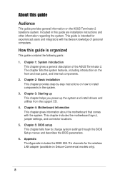
... adapter (with • ASUS P4R8T motherboard • 3-in-1 PCI card* • Floppy disk drive • 7-in-1 storage card reader • FM radio module and radio antenna • LED panel • CPU fan and heatsink assembly 2. Item Description T2-R Models Commercial Deluxe Deluxe Standard 1. AC power cable 3. System package contents Check your Terminator 2 system package for...
... adapter (with • ASUS P4R8T motherboard • 3-in-1 PCI card* • Floppy disk drive • 7-in-1 storage card reader • FM radio module and radio antenna • LED panel • CPU fan and heatsink assembly 2. Item Description T2-R Models Commercial Deluxe Deluxe Standard 1. AC power cable 3. System package contents Check your Terminator 2 system package for...
T2-R User Manual
Page 11
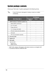
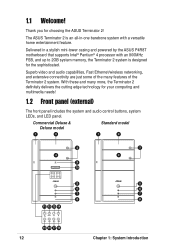
MODE ASUS Terminator 2 barebone system The chapter lists the system features, including introduction on the front and rear panel, and internal components. System introduction Chapter 1 This chapter gives a general description of the ASUS Terminator 2.
MODE ASUS Terminator 2 barebone system The chapter lists the system features, including introduction on the front and rear panel, and internal components. System introduction Chapter 1 This chapter gives a general description of the ASUS Terminator 2.
T2-R User Manual
Page 12
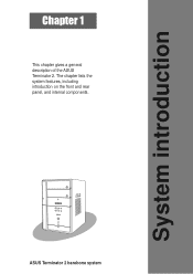
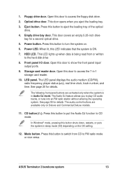
Delivered in -one barebone system with an 800MHz FSB, and up to 2GB system memory, the Terminator 2 system is designed for the sophisticated. Commercial Deluxe & Deluxe model Standard model 1 2 1 2 3 4 9 10 MODE 5 6 7 8 11 12 13 14 MODE 3 4 5 6 7 8 15 16 17 18 12 Chapter 1: System...audio control buttons, system LEDs, and LED panel. With these and many features of the Terminator 2 system. The ASUS Terminator 2 is an all-in a stylish mini-tower casing and powered by the ASUS P4R8T motherboard that supports Intel® Pentium® 4 processor with a versatile home entertainment ...
Delivered in -one barebone system with an 800MHz FSB, and up to 2GB system memory, the Terminator 2 system is designed for the sophisticated. Commercial Deluxe & Deluxe model Standard model 1 2 1 2 3 4 9 10 MODE 5 6 7 8 11 12 13 14 MODE 3 4 5 6 7 8 15 16 17 18 12 Chapter 1: System...audio control buttons, system LEDs, and LED panel. With these and many features of the Terminator 2 system. The ASUS Terminator 2 is an all-in a stylish mini-tower casing and powered by the ASUS P4R8T motherboard that supports Intel® Pentium® 4 processor with a versatile home entertainment ...
T2-R User Manual
Page 13
... on. 6. Eject button. Power button. When lit, this LED indicates that the system is in sleep mode (S3) depending on Deluxe and Commercial Deluxe models. 11. Storage card reader door. The audio control buttons are activated only when the system is ON. 7. Optical drive door....audio tracks, or tune into an FM radio station without entering the operating system. The Audio DJ feature allows you eject the loading tray. 3. ASUS Terminator 2 barebone system 13 Press this door to the hard disk drive 8. The LED panel displays the audio medium (CD/FM), radio frequency, player...
... on. 6. Eject button. Power button. When lit, this LED indicates that the system is in sleep mode (S3) depending on Deluxe and Commercial Deluxe models. 11. Storage card reader door. The audio control buttons are activated only when the system is ON. 7. Optical drive door....audio tracks, or tune into an FM radio station without entering the operating system. The Audio DJ feature allows you eject the loading tray. 3. ASUS Terminator 2 barebone system 13 Press this door to the hard disk drive 8. The LED panel displays the audio medium (CD/FM), radio frequency, player...
T2-R User Manual
Page 15
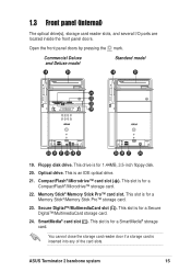
... Pro™ storage card. 23. Memory Stick®/Memory Stick Pro™ card slot. This slot is for a SmartMedia® storage card. ASUS Terminator 2 barebone system 15 This is for a CompactFlash®/Microdrive™ storage card. 22. Optical drive. This slot is an IDE optical drive. 21...;/MultimediaCard slot ( ). CompactFlash®/Microdrive™ card slot ( ). Open the front panel doors by pressing the mark. Floppy disk drive. Commercial Deluxe and Deluxe model 19 20 Standard model 19 20 21 22 23 24 MODE 25 26 27 28 29 30 25 26 27 30 19.
... Pro™ storage card. 23. Memory Stick®/Memory Stick Pro™ card slot. This slot is for a SmartMedia® storage card. ASUS Terminator 2 barebone system 15 This is for a CompactFlash®/Microdrive™ storage card. 22. Optical drive. This slot is an IDE optical drive. 21...;/MultimediaCard slot ( ). CompactFlash®/Microdrive™ card slot ( ). Open the front panel doors by pressing the mark. Floppy disk drive. Commercial Deluxe and Deluxe model 19 20 Standard model 19 20 21 22 23 24 MODE 25 26 27 28 29 30 25 26 27 30 19.
T2-R User Manual
Page 17
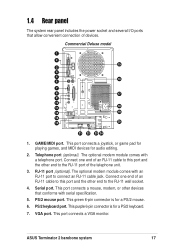
PS/2 keyboard port. ASUS Terminator 2 barebone system 17 Telephone port (optional). Connect one end of an RJ-11 cable to this port and the other devices that allow convenient connection ... an RJ-11 cable to this port and the other end to the RJ-11 wall socket. 4. RJ-11 port (optional). PS/2 mouse port. Commercial Deluxe model 1 2 15 3 4 5 16 6 7 8 17 9 10 18 11 12 19 13 14 20 21 22 23 24 1. Serial port. GAME/MIDI port. This port connects a joystick...
PS/2 keyboard port. ASUS Terminator 2 barebone system 17 Telephone port (optional). Connect one end of an RJ-11 cable to this port and the other devices that allow convenient connection ... an RJ-11 cable to this port and the other end to the RJ-11 wall socket. 4. RJ-11 port (optional). PS/2 mouse port. Commercial Deluxe model 1 2 15 3 4 5 16 6 7 8 17 9 10 18 11 12 19 13 14 20 21 22 23 24 1. Serial port. GAME/MIDI port. This port connects a joystick...
T2-R User Manual
Page 19
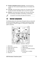
...Deluxe models only.) This green LED blinks when the wireless LAN adapter is on installing other system components. 1 6 3 2 9 10 11 8 7 4 5 1. Optical drive 2. ASUS... P4R8T motherboard 8. See page 58 for the wireless LAN adapter LED indications. 1.5 Internal components The illustration below is the internal view of the wireless LAN adapter. 23. The installed components are labeled for instructions on but has no activity. 24. Front panel cover 5. DIMM sockets 9. Link LED. (Commercial Deluxe... adapter antenna connector. (Commercial Deluxe models only.) This connects the...
...Deluxe models only.) This green LED blinks when the wireless LAN adapter is on installing other system components. 1 6 3 2 9 10 11 8 7 4 5 1. Optical drive 2. ASUS... P4R8T motherboard 8. See page 58 for the wireless LAN adapter LED indications. 1.5 Internal components The illustration below is the internal view of the wireless LAN adapter. 23. The installed components are labeled for instructions on but has no activity. 24. Front panel cover 5. DIMM sockets 9. Link LED. (Commercial Deluxe... adapter antenna connector. (Commercial Deluxe models only.) This connects the...
T2-R User Manual
Page 21
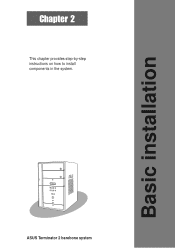
Basic installation Chapter 2 This chapter provides step-by-step instructions on how to install components in the system. MODE ASUS Terminator 2 barebone system
Basic installation Chapter 2 This chapter provides step-by-step instructions on how to install components in the system. MODE ASUS Terminator 2 barebone system
T2-R User Manual
Page 23
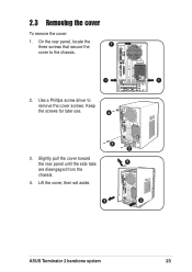
On the rear panel, locate the three screws that secure the 1 cover to remove the cover screws. 2.3 Removing the cover To remove the cover: 1. Lift the cover, then set aside. 2 2 4 3 3 ASUS Terminator 2 barebone system 23 Slightly pull the cover toward the rear panel until the side tabs are disengaged from the chassis. 4. Keep the screws for later use. 2 3. Use a Phillips screw driver to the chassis. 1 1 2.
On the rear panel, locate the three screws that secure the 1 cover to remove the cover screws. 2.3 Removing the cover To remove the cover: 1. Lift the cover, then set aside. 2 2 4 3 3 ASUS Terminator 2 barebone system 23 Slightly pull the cover toward the rear panel until the side tabs are disengaged from the chassis. 4. Keep the screws for later use. 2 3. Use a Phillips screw driver to the chassis. 1 1 2.
T2-R User Manual
Page 25
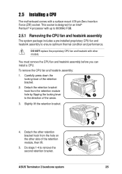
.... 2.5.1 Removing the CPU fan and heatsink assembly The system package includes a pre-installed proprietary CPU fan and heatsink assembly to remove the second retention bracket. 4 ASUS Terminator 2 barebone system 3 25 2.5 Installing a CPU The motherboard comes with other side of the arrow. 3. Slightly lift the retention bracket. 4.
.... 2.5.1 Removing the CPU fan and heatsink assembly The system package includes a pre-installed proprietary CPU fan and heatsink assembly to remove the second retention bracket. 4 ASUS Terminator 2 barebone system 3 25 2.5 Installing a CPU The motherboard comes with other side of the arrow. 3. Slightly lift the retention bracket. 4.
T2-R User Manual
Page 27
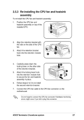
... the CPU fan cable to connect the CPU fan connector! Do not forget to the CPU fan connector on the side of the retention bracket. 5. ASUS Terminator 2 barebone system 27 Align the retention bracket with the rails on the motherboard. Hardware monitoring errors might occur if you fail to re-install the...
... the CPU fan cable to connect the CPU fan connector! Do not forget to the CPU fan connector on the side of the retention bracket. 5. ASUS Terminator 2 barebone system 27 Align the retention bracket with the rails on the motherboard. Hardware monitoring errors might occur if you fail to re-install the...
T2-R User Manual
Page 29
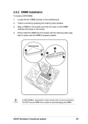
Retaining clips 3 2 4 2 4 1 A DDR DIMM is properly seated. Align a DIMM on the socket such that it fits in place and the DIMM is keyed with a notch so that the notch on the DIMM matches the break on the motherboard. 2. ASUS Terminator 2 barebone system 29 Firmly insert the DIMM into a socket to avoid damaging the DIMM! Unlock a socket by pressing the retaining clips outward. 3. 2.6.2 DIMM installation To install a DDR DIMM. 1. Locate the two DIMM sockets on the socket. 4. DO NOT force a DIMM into the socket until the retaining clips snap back in only one direction.
Retaining clips 3 2 4 2 4 1 A DDR DIMM is properly seated. Align a DIMM on the socket such that it fits in place and the DIMM is keyed with a notch so that the notch on the DIMM matches the break on the motherboard. 2. ASUS Terminator 2 barebone system 29 Firmly insert the DIMM into a socket to avoid damaging the DIMM! Unlock a socket by pressing the retaining clips outward. 3. 2.6.2 DIMM installation To install a DDR DIMM. 1. Locate the two DIMM sockets on the socket. 4. DO NOT force a DIMM into the socket until the retaining clips snap back in only one direction.
T2-R User Manual
Page 31
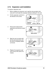
... slot. 5. Metal brackets 4. 2.7.2 Expansion card installation To install an expansion card. 1. Replace the expansion card lock to secure the card to the chassis. 4 PCI card 5 ASUS Terminator 2 barebone system 31
... slot. 5. Metal brackets 4. 2.7.2 Expansion card installation To install an expansion card. 1. Replace the expansion card lock to secure the card to the chassis. 4 PCI card 5 ASUS Terminator 2 barebone system 31
T2-R User Manual
Page 33
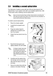
...3 3 4 4 5. Set your system came with the holes on the bay as shown. 7. Locate the front panel cover hooks. 3. On Deluxe models, disconnect the LED panel and the front audio button panel cables from the chassis. 4. Place the chassis upright. 2. If your second optical drive as...with two 5.25-inch drive bays for two optical drives. 2.8 Installing a second optical drive The Terminator 2 system comes with two screws on one side of the bay. 6 5 7 ASUS Terminator 2 barebone system 33 Press the hooks inward to this section when installing a second optical drive....
...3 3 4 4 5. Set your system came with the holes on the bay as shown. 7. Locate the front panel cover hooks. 3. On Deluxe models, disconnect the LED panel and the front audio button panel cables from the chassis. 4. Place the chassis upright. 2. If your second optical drive as...with two 5.25-inch drive bays for two optical drives. 2.8 Installing a second optical drive The Terminator 2 system comes with two screws on one side of the bay. 6 5 7 ASUS Terminator 2 barebone system 33 Press the hooks inward to this section when installing a second optical drive....
T2-R User Manual
Page 35
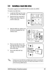
... from the chassis hooks. Keep the screw for later use. 1 2 3. Secure the HDD with a Philips screw driver. Align the HDD and HDD tray screw holes. 5. ASUS Terminator 2 barebone system 35 To install a hard disk drive: 1. 2.9 Installing a hard disk drive The system supports one UltraATA133 IDE hard disk drive (HDD). Locate the HDD...
... from the chassis hooks. Keep the screw for later use. 1 2 3. Secure the HDD with a Philips screw driver. Align the HDD and HDD tray screw holes. 5. ASUS Terminator 2 barebone system 35 To install a hard disk drive: 1. 2.9 Installing a hard disk drive The system supports one UltraATA133 IDE hard disk drive (HDD). Locate the HDD...
T2-R User Manual
Page 37
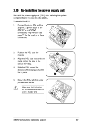
...) after installing the system components and reconnecting the cables. Position the PSU over the chassis. 3. Secure the PSU with the CPU and/or chassis fans. 5 ASUS Terminator 2 barebone system 37 Align the PSU side hook with the metal slot on the side of these 1 connectors. 1 2. See page 77 for the location of...
...) after installing the system components and reconnecting the cables. Position the PSU over the chassis. 3. Secure the PSU with the CPU and/or chassis fans. 5 ASUS Terminator 2 barebone system 37 Align the PSU side hook with the metal slot on the side of these 1 connectors. 1 2. See page 77 for the location of...
T2-R User Manual
Page 39
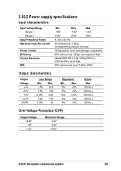
... Max -5% +5% -5% +5% -10% +10% -5% +5% -5% +5% Ripple Max 50mVp-p 120mVp-p 150mVp-p 60mVp-p 60mVp-p Over-Voltage Protection (OVP) Output Voltage +3.3V +5V +12V Maximum Voltage 4.6V 6.5V 15.6V ASUS Terminator 2 barebone system 39
... Max -5% +5% -5% +5% -10% +10% -5% +5% -5% +5% Ripple Max 50mVp-p 120mVp-p 150mVp-p 60mVp-p 60mVp-p Over-Voltage Protection (OVP) Output Voltage +3.3V +5V +12V Maximum Voltage 4.6V 6.5V 15.6V ASUS Terminator 2 barebone system 39
T2-R User Manual
Page 41
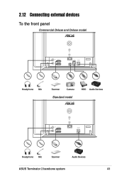
2.12 Connecting external devices To the front panel Commercial Deluxe and Deluxe model Headphone Mic Scanner Camera Standard model HDD Audio Devices Headphone Mic Scanner Audio Devices ASUS Terminator 2 barebone system 41
2.12 Connecting external devices To the front panel Commercial Deluxe and Deluxe model Headphone Mic Scanner Camera Standard model HDD Audio Devices Headphone Mic Scanner Audio Devices ASUS Terminator 2 barebone system 41
T2-R User Manual
Page 43
MODE ASUS Terminator 2 barebone system Starting up Chapter 3 This chapter helps you power up the system and install drivers and utilities from the support CD.
MODE ASUS Terminator 2 barebone system Starting up Chapter 3 This chapter helps you power up the system and install drivers and utilities from the support CD.